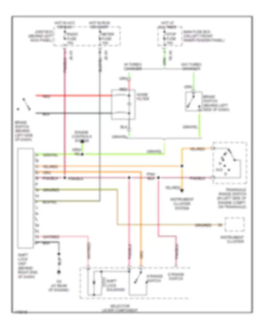
AUTOMOTIVE ELECTRICIANS PORTAL

SHIFT INTERLOCK – Mazda Protege ES 2003 – SYSTEM WIRING DIAGRAMS

SHIFT INTERLOCK

Shift Interlock Wiring Diagram for Mazda Protege ES 2003

Shift Interlock Wiring Diagram for Mazda Protege ES 2003 https://portal-diagnostov.com/license.html
https://portal-diagnostov.com/license.html Automotive Electricians Portal FZCO Automotive Electricians Portal FZCO
Get access to all wiring diagrams of the carDownload PDF file

List of elements for Shift Interlock Wiring Diagram for Mazda Protege ES 2003:

  • Brake switch (behind left side of dash)
  • D range switch
  • Engine controls system
  • Fb-06
  • G4 (at rear of engine)
  • Hot at all times
  • Hot in acc or run
  • Hot in run or start
  • Instrument cluster
  • Instrument cluster system
  • Jb-03
  • Jb-04
  • Joint box (behind left kick panel)
  • Main fuse box (on left front inner fender panel)
  • Meter fuse 10a
  • N range switch
  • N-d
  • Noise filter
  • Radio fuse 15a
  • Red
  • Selector lever component
  • Shift lock solenoid
  • Shift lock unit (behind right end of dash)
  • Stop fuse 15a
  • Transaxle range switch (in left side of engine compt, on transaxle)
  • W/ turbo changer
  • W/o turbo changer