SHIFT INTERLOCK
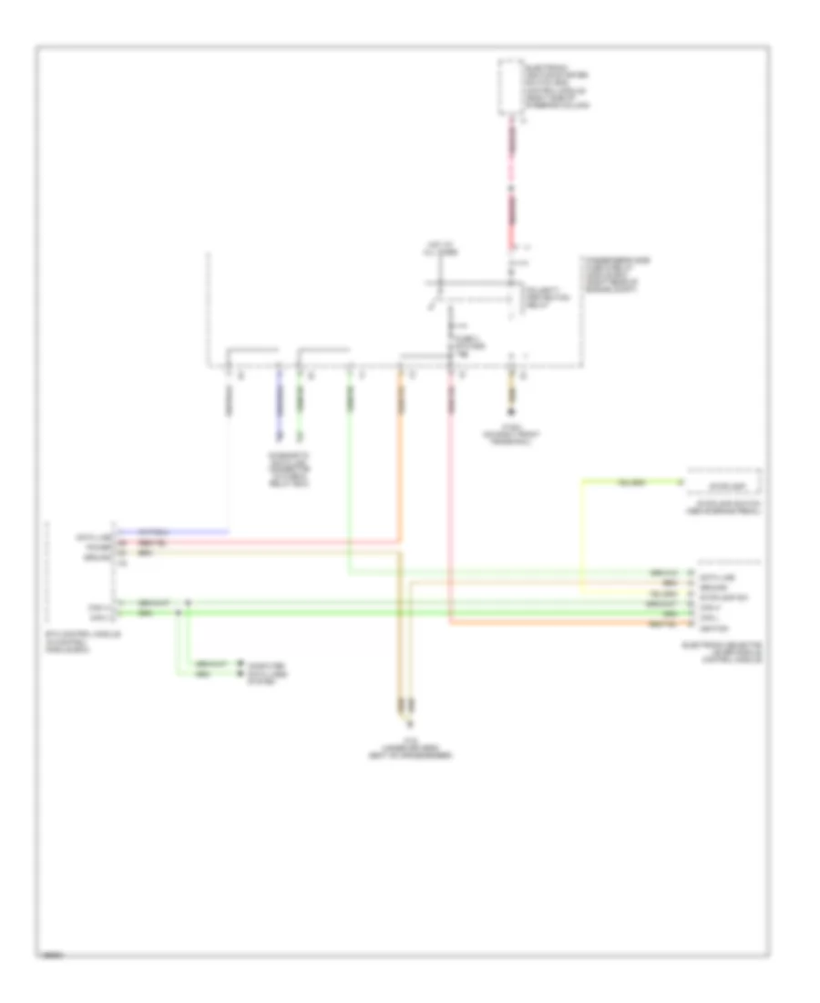
Shift Interlock Wiring Diagram for Mercedes-Benz E320 4Matic 2003

List of elements for Shift Interlock Wiring Diagram for Mercedes-Benz E320 4Matic 2003:
- Can-c h
- Can-c l
- Central gateway control module (left front footwell.)
- Circuit 87 relay, chassis
- Computer data lines system
- Di control module (right side of steering column)
- Driver side sam control module with fuse/relay module (left rear of engine compartment)
- Electric control unit (part of transmission)
- Electric steering lock control module (left front footwell)
- Electronic selector lever module control module (center console)
- Engine control module (me-sfi) (left rear of eng compt)
- Esp/sps/bas control module (left rear of eng compt)
- Etc control module (right front footwell)
- Fuse 45 7.5a
- Gear display sensor (under center console)
- Gnd
- Hot at all times
- Instrument cluster
- Keyless go start/stop pushbutton (if equipped)
- Left voltage distributor connector (left front door sill)
- Nca
- Solid state
- W/ 5 speed transmission
- W/ 7 speed transmission
- W15/1 (right front footwell)
Shift Interlock Wiring Diagram, Wagon for Mercedes-Benz E320 4Matic 2003
List of elements for Shift Interlock Wiring Diagram, Wagon for Mercedes-Benz E320 4Matic 2003:
- A pnk/red
- Can (+)
- Can (-)
- Can h
- Can l
- Computer data lines system
- Data line
- Diagnostic data link connector (in fuse & relay box)
- Electronic ignition-starter switch (eis) control module (right side of steering column)
- Electronic selector lever module control module
- Etc control module (in control module box)
- Fuse 3 etc/ads 10a
- Ground
- Hot at all times
- Ignition
- Passenger's side fuse & relay module box (right rear of engine compt)
- Pnk/red
- Polarity protection relay
- Power
- Stoplamp
- Stoplamp sw
- Stoplamp switch (above brake pedal)
- W16/4 (on right front frame rail)
- W18 (under driver's seat on crossmember)