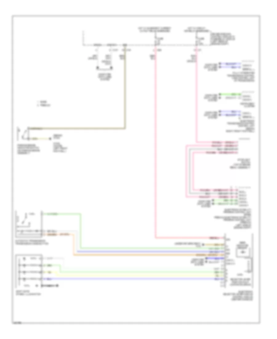
SHIFT INTERLOCK
Shift Interlock Wiring Diagram for Mercedes-Benz E350 2012
List of elements for Shift Interlock Wiring Diagram for Mercedes-Benz E350 2012:
- (sedan) w15/2
- (under driver's seat) w18
- 30g
- 58d
- Automatic transmission transmission mode button
- Base
- Bls_h
- Bls_l
- Bls_m
- C10t
- C19i
- C7i
- C9g
- Can c h
- Can c l
- Can d h
- Can d l
- Can e h
- Can e l
- Can-c h
- Can-c l
- Computer data lines system
- Driver side sam control module w/ fuse/relay module (left rear of engine compt)
- Electronic selector lever module control module (center console)
- Electronic stability program control unit (base) premium electronic stability program control unit (premium) (left side of engine compt)
- Electronic transmission control control unit (sedan) (right front footwell)
- Fully integrated transmission control (vgs) control unit (in transmission)
- Fuse 5a
- Fuse 7.5a
- Gear indicator sensor
- Hot w/ circuit 15r relay energized
- Hot w/ quiescent current cutout relay energized
- Instrument cluster
- Nca
- P r n d- d+
- Parking brake indicator switch (on parking brake assembly)
- Premium
- Selector lever position r & p locking solenoid
- Shift gate symbol illumination
- Sig
- Stoplight switch (top of brake pedal assembly)
- W15/5 (coupe) (left front footwell )
 Русский