SHIFT INTERLOCK
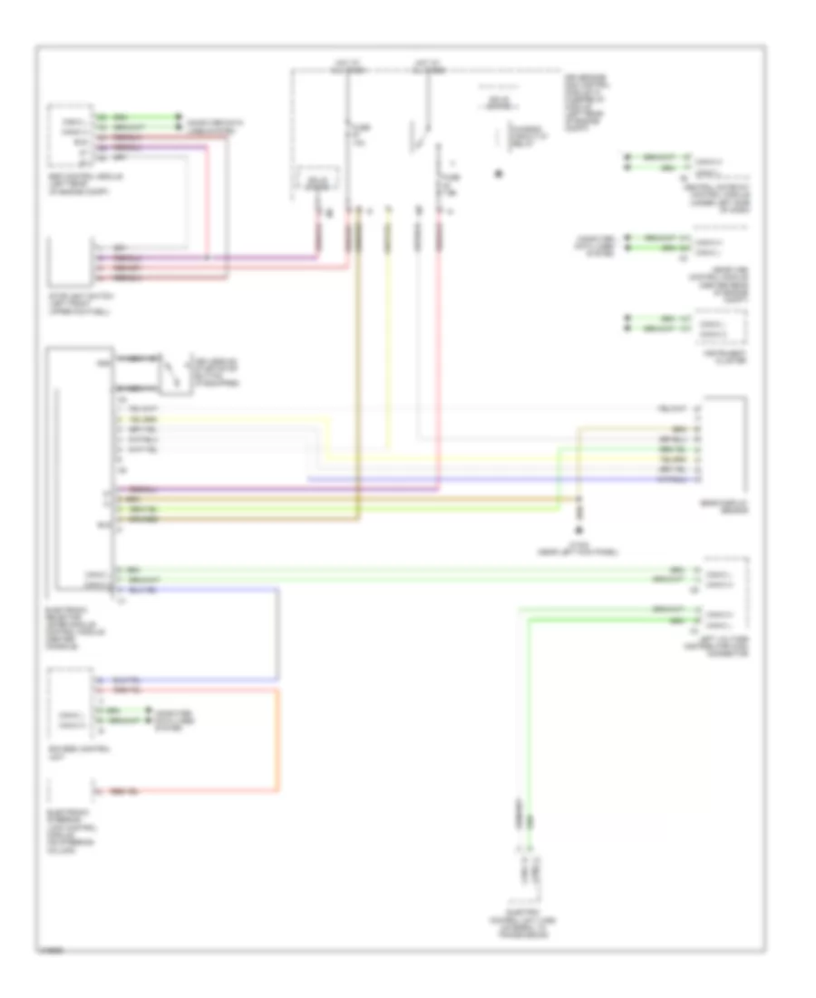
Shift Interlock Wiring Diagram for Mercedes-Benz E550 4Matic 2009
List of elements for Shift Interlock Wiring Diagram for Mercedes-Benz E550 4Matic 2009:
- Bls
- Can-c h
- Can-c l
- Central gateway control module (under left side of dash)
- Chassis circuit 87 relay
- Computer data lines system
- Driver side sam control module w/ fuse/relay module (left rear of engine compt)
- Eis (ezs) control unit
- Electric control unit (vgs) (integral to transmission)
- Electronic selector lever module control module (center console)
- Electronic steering lock control module (on steering column)
- Esp control module (left rear of engine compt)
- Fuse 10a
- Fuse 7.5a
- Gear display sensor
- Gnd
- Hot at all times
- Instrument cluster
- Keyless go start/stop button (if equipped)
- Left voltage distributor (can) connector
- Me-sfi (me) control module (center rear of engine compt)
- Nca
- Solid state
- Stoplight switch (left front upper footwell)
- W15/2 (near left kick panel)
 English