SHIFT INTERLOCK
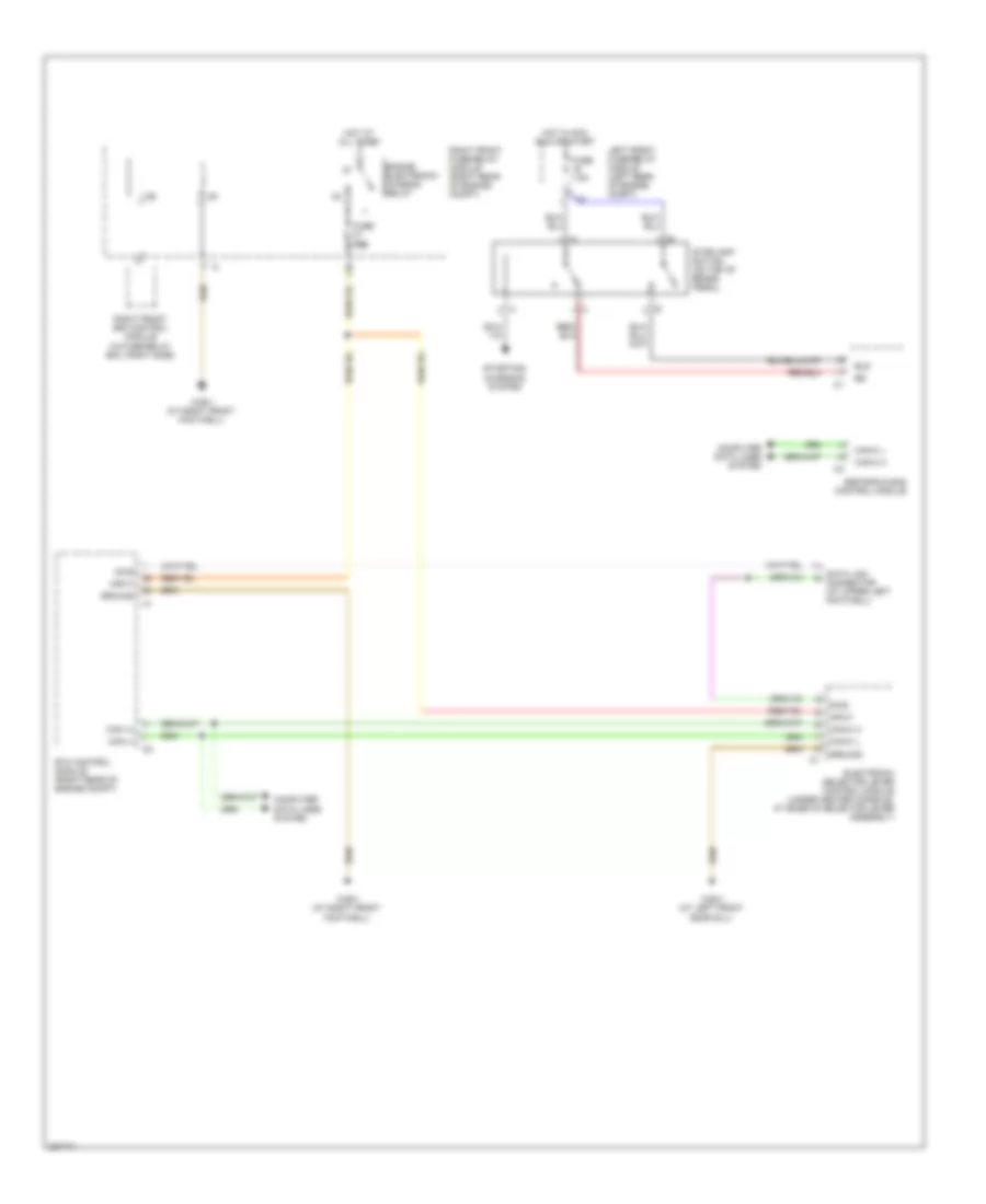
Shift Interlock Wiring Diagram for Mercedes-Benz S430 4Matic 2006
List of elements for Shift Interlock Wiring Diagram for Mercedes-Benz S430 4Matic 2006:
- Bls
- Can (+)
- Can (-)
- Can-c h
- Can-c l
- Computer data lines system
- Data link connector (at upper left footwell)
- Diag
- Electronic selector lever control module (under center console, at base of selector lever assembly)
- Engine electronic/ chassis relay
- Esp/sps & bas control module
- Etc control module (right rear of engine compt)
- Fuse 15a
- Fuse 7.5a
- Ground
- Hot at all times
- Hot in acc, run or start
- Input
- L18
- Left front fuse/relay module (left rear of engine compt)
- Right front fuse/relay module (right rear of engine compt)
- Right front sam control module (in fuse/relay box, right side)
- Starting/ charging system
- Stoplamp switch (on top of brake pedal)
- W28/1 (at left front door sill)
- W36/1 (at right front footwell)
 English