SHIFT INTERLOCK
Shift Interlock Wiring Diagram for Mercedes-Benz SLK350 2006
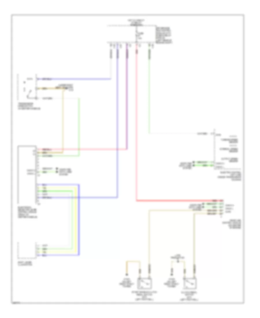
List of elements for Shift Interlock Wiring Diagram for Mercedes-Benz SLK350 2006:
- (under right seat, on floor) w19
- C10
- C22
- Can-c h
- Can-c l
- Clutch pedal switch (m/t) (left footwell)
- Computer data lines system
- Diag
- Driver-side sam control module with fuse & relay module (left rear of engine compt)
- Electric control unit (vgs) (inside transmission housing)
- Electronic selector lever control module (front of center console)
- Fuse 10a
- Hot w/ circuit 87 relay energizied
- Internal speed sensor
- Kup2
- Late production
- Me-sfi (me) control module (on center of engine)
- Output speed sensor
- Red
- Shift lever illumination
- Start enable clutch pedal switch (m/t) (left footwell)
- Transmission mode switch (in center console)
- Turbine speed sensor
- W16/3 (on left front strut tower)
 English