SHIFT INTERLOCK
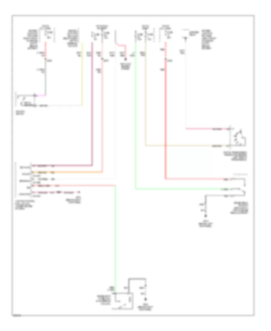
Shift Interlock Wiring Diagram for Mercury Grand Marquis LS 2009
List of elements for Shift Interlock Wiring Diagram for Mercury Grand Marquis LS 2009:
- Anti-lock brakes system
- Battery junction box (bjb) (right front of engine compt, behind battery)
- Brake pedal position (bpp) switch (top of brake pedal support)
- Brake shift interlock (on steering column)
- Brake sw
- Bsi
- C2145a
- C2145b
- Central junction box (cjb) (below dash, left of steering column)
- Digital transmission range (dtr) sensor (left side of transmission)
- Fuse 10a
- Fuse 20a
- Fuse 30a
- Fuse 5a
- Fuse 7.5a
- G201 (behind right kick panel)
- G204 (behind right kick panel)
- G212 (behind left kick panel)
- Hot at all times
- Hot in run or start
- Hot in start
- Ignition switch
- Key in sw
- Key-in ignition
- Lighting control module (lcm) (under center of dash)
- Logic gnd
- Red
- Run/st
- S200
- S204
- S210
- S246
- S267
- S276
- Starter relay
 English