SHIFT INTERLOCK
Shift Interlock Wiring Diagram, Evolution for Mitsubishi Lancer GT 2012

List of elements for Shift Interlock Wiring Diagram, Evolution for Mitsubishi Lancer GT 2012:
- (behind center of dash) g6
- C-130
- C-27
- C-304
- C-317
- C-35
- Can transceiver
- Circuit
- Combination meter
- Computer data lines system
- Cpu
- Etacs-ecu (on rear of junction block, behind left end of dash)
- Fuse 15a
- Fuse 7.5a
- High side switch
- Hot at all times
- Hot in on or start
- Ig1 relay
- J/c c-101
- Lcd shift position
- Lever position sensor (p)
- Low side switch
- Nca
- Pnk
- Red
- Shift lever (tc-sst: center console)
- Shift lever position indicator panel
- Shift lock solenoid
- Stoplight switch (under left side of dash)
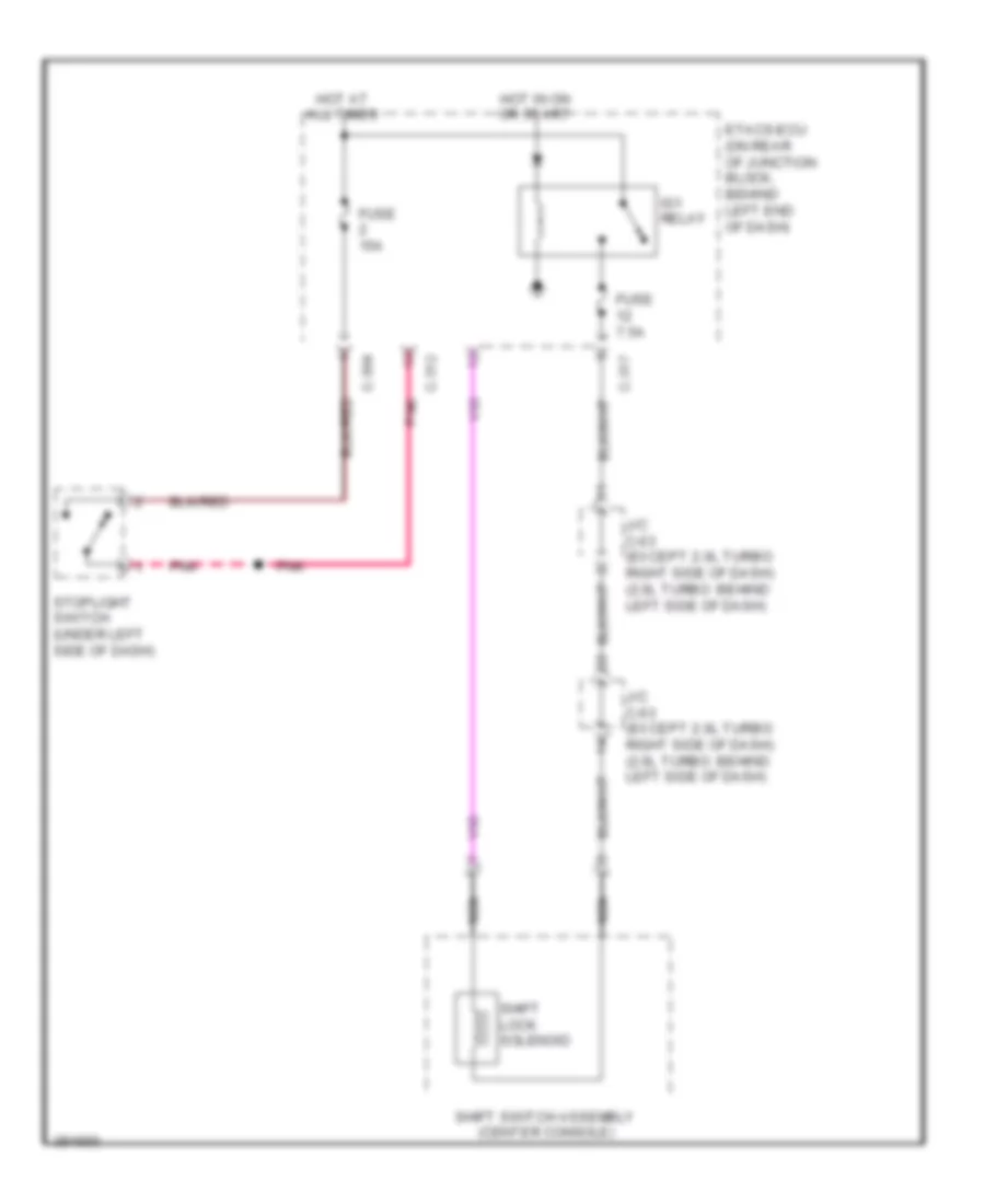
Shift Interlock Wiring Diagram, Except Evolution, CVT for Mitsubishi Lancer GT 2012
List of elements for Shift Interlock Wiring Diagram, Except Evolution, CVT for Mitsubishi Lancer GT 2012:
- C-304
- C-312
- C-317
- Etacs-ecu (on rear of junction block, behind left end of dash)
- Fuse 15a
- Fuse 7.5a
- Hot at all times
- Hot in on or start
- Ig1 relay
- J/c c-03 (except 2.0l turbo: right side of dash) (2.0l turbo: behind left side of dash)
- Nca
- Pnk
- Shift lock solenoid
- Shift switch assembly (center console)
- Stoplight switch (under left side of dash)
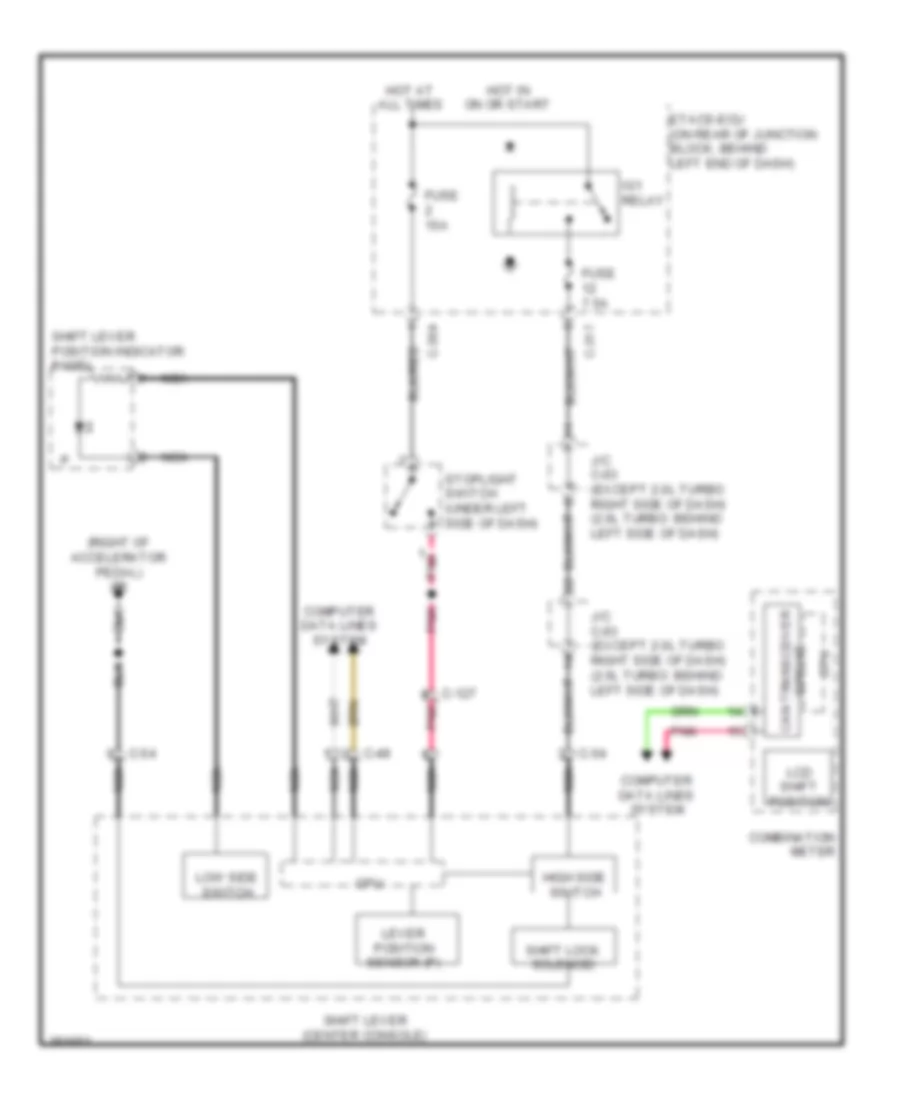
Shift Interlock Wiring Diagram, Except Evolution, TC-SST for Mitsubishi Lancer GT 2012
List of elements for Shift Interlock Wiring Diagram, Except Evolution, TC-SST for Mitsubishi Lancer GT 2012:
- (right of accelerator pedal) g5
- C-127
- C-304
- C-317
- C-49
- C-54
- Can transceiver
- Circuit
- Combination meter
- Computer data lines system
- Cpu
- Etacs-ecu (on rear of junction block, behind left end of dash)
- Fuse 15a
- Fuse 7.5a
- High side switch
- Hot at all times
- Hot in on or start
- Ig1 relay
- J/c c-03 (except 2.0l turbo: right side of dash) (2.0l turbo: behind left side of dash)
- Lcd shift position
- Lever position sensor (p)
- Low side switch
- Nca
- Pnk
- Shift lever (center console)
- Shift lever position indicator panel
- Shift lock solenoid
- Stoplight switch (under left side of dash)