SHIFT INTERLOCK
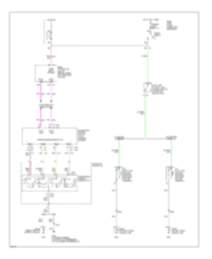
Shift Interlock Wiring Diagram for Pontiac Bonneville GXP 2005
List of elements for Shift Interlock Wiring Diagram for Pontiac Bonneville GXP 2005:
- (3.8l)
- (3.8l) (4.6l)
- (4.6l)
- 3.8l
- 4.6l
- A/t shift lock control solenoid (on floor shifter assembly)
- A12
- Automatic transaxle
- B12
- C2 b
- Computer data lines system
- Data line
- F c
- G105
- G108 (in engine harness, 18 cm from a/c compressor clutch connector breakout)
- G200
- G201
- Hot at all times
- Hot in on
- Park relay
- Park relay control
- Powertrain control module (in air cleaner housing)
- Prk/rev fuse 10a
- Rear fuse block (under left rear seat)
- Rear integration module (behind upper left rear seat cushion)
- S130
- S225
- S228
- Sig a
- Sig b
- Sig c
- Sig d
- Sp105 (below ignition control module)
- Sp200 (on left front door pillar)
- Sp201 (on right front door pillar)
- Stop lamp/ at shift lock control switch (lower left side of dash)
- Transmission internal mode switch
- Transmission range switch
- W/ center console
- W/o center console
 Русский