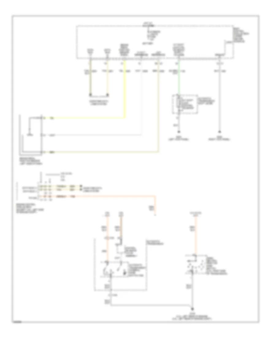
SHIFT INTERLOCK
Shift Interlock Wiring Diagram for Pontiac G6 GXP 2010
List of elements for Shift Interlock Wiring Diagram for Pontiac G6 GXP 2010:
- (pnp) switch (3.5l: right side of transmission)
- 2.4l
- 2.4l & 3.5l (a/t)
- 3.5l & 3.9l
- 3.6l
- 3.6l (a/t)
- 3.9l (a/t)
- 5 volt reference
- A/t shift lock control solenoid
- Automatic transmission
- Automatic transmission internal mode switch (ims)
- Automatic transmission shift lever
- Battery
- Body control module (bcm) (under center console)
- Brake pedal position sensor (left side of dash)
- Brake pedal position sensor signal
- Computer data lines system
- Control solenoid valve assembly
- Data bus (+)
- Data bus (-)
- Engine control module (ecm) (except 3.6l: left side of engine compt)
- G105 (2.4l: left rear of engine) (3.5l: left rear of engine compt)
- G303 (left kick panel)
- G305 (right kick panel)
- Ground
- Hot at all times
- Interior lights fuse 10a
- K x100
- Logic
- Low reference
- Nca
- P/n sig
- Park/ neutral position
- Tan
- Tan/
- W x100
 Русский