SHIFT INTERLOCK
Ignition Lock Solenoid Wiring Diagram for Pontiac G8 GXP 2009

List of elements for Ignition Lock Solenoid Wiring Diagram for Pontiac G8 GXP 2009:
- Automatic transmission shift lever
- G201 (behind right kick panel)
- Hot w/ accy relay 8 energized
- I/p fuse block (behind left kick panel)
- Ignition lock cylinder control solenoid
- J219
- S/roof atsl fuse 16 10a
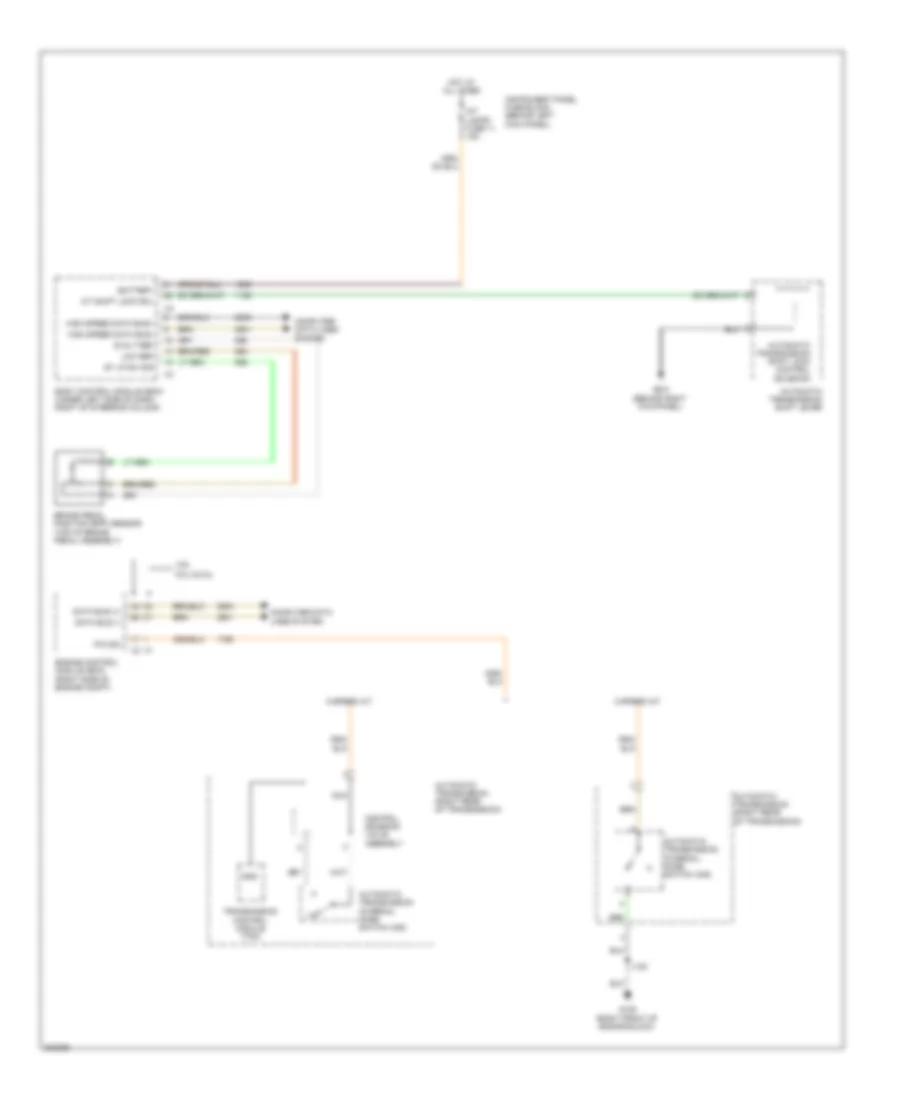
Shift Interlock Wiring Diagram for Pontiac G8 GXP 2009
List of elements for Shift Interlock Wiring Diagram for Pontiac G8 GXP 2009:
- 3.6l
- 5 speed a/t
- 5volt ref
- 6 speed a/t
- 6.0l & 6.2l
- A/t shift lock sol
- Automatic transmission (right rear of transmission)
- Automatic transmission internal mode switch (ims)
- Automatic transmission shift lever
- Automatic transmission shift lock control solenoid
- Battery
- Body control module (bcm) (under left side of dash, right of steering column)
- Brake pedal position (bpp) sensor (top of brake pedal assembly)
- Computer data lines system
- Control solenoid valve assembly
- Data bus (+)
- Data bus (-)
- Engine control module (ecm) (right side of engine compt)
- G106 (right front of engine block)
- G201 (behind right kick panel)
- Gnd
- High speed data bus+
- High speed data bus-
- Hot at all times
- Instrument panel fuse block (behind left kick panel)
- Int lamps fuse 11 15a
- J122
- Low ref
- Nca
- P/n sig
- St lp sw sig
- Transmission control module (tcm)