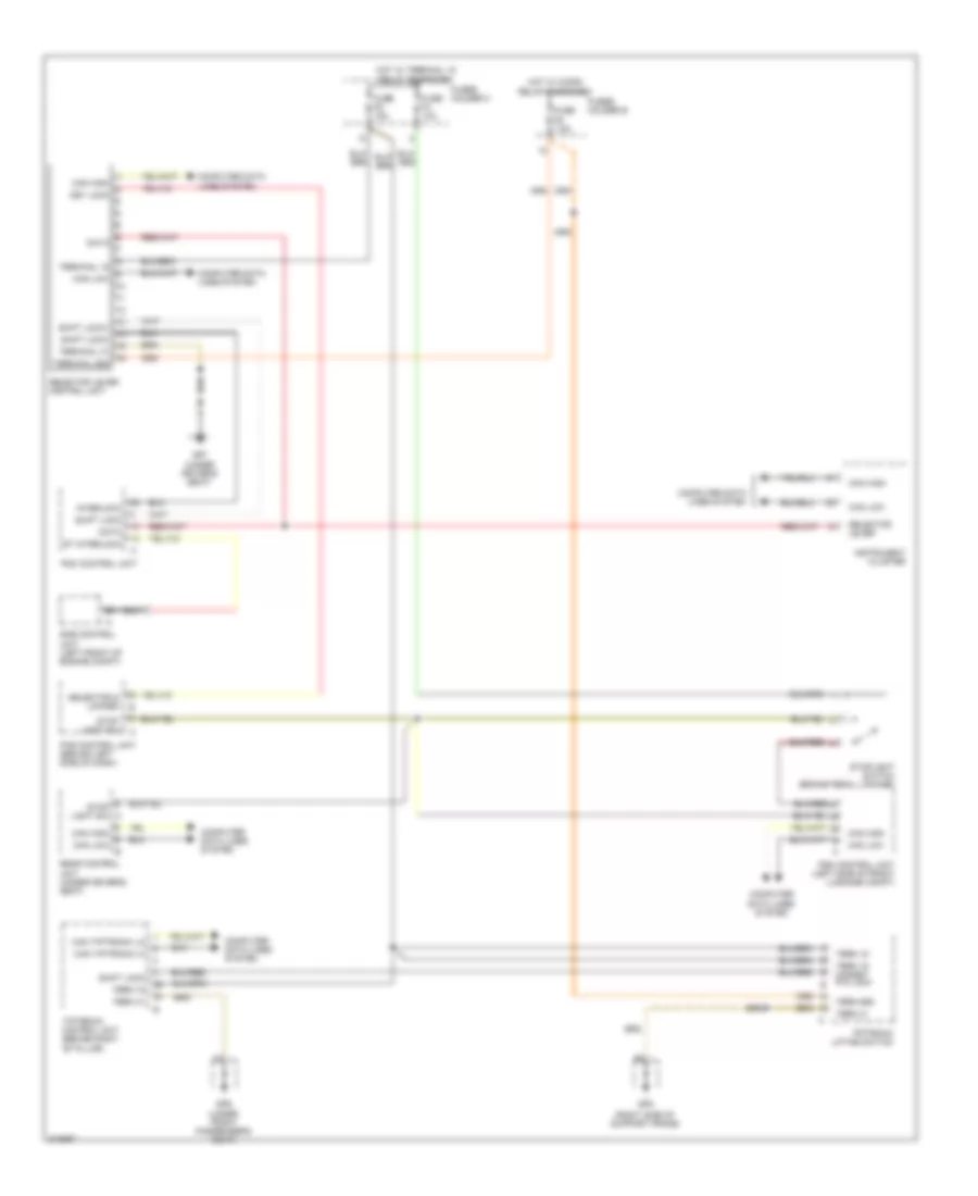
SHIFT INTERLOCK
Shift Interlock Wiring Diagram for Porsche 911 Carrera 2009
List of elements for Shift Interlock Wiring Diagram for Porsche 911 Carrera 2009:
- (right side of support frame)
- Can high
- Can high can low
- Can low
- Can tiptronic hi
- Can tiptronic lo
- Computer data lines system
- Data
- Dme control unit (left front of engine compt)
- Fuse f4 10a
- Fuse f5 15a
- Fuse f9 7.5a
- Fuses holder b
- Fuses holder c
- Gp5
- Gp6 (under front passenger's seat)
- Gp7 (under driver's seat)
- Hot w/ micro relay energized
- Hot w/ terminal 15 relay energized
- Instrument cluster
- Interlock
- Key lock
- Pas control unit (behind left side of dash)
- Pdk control unit
- Psm control unit (left side of front luggage compt)
- Rear control unit (under driver's seat)
- Selector & locked
- Selector lever
- Selector lever control unit
- Shift lock
- Shift lock+
- Shift lock-
- St interlock
- Stop light sw
- Stop light sw a
- Stoplight switch (brake pedal linkage)
- Term 15
- Term 15 magnet p/n lock
- Term 31
- Term 86s
- Terminal 15
- Terminal 31
- Terminal 86s
- Tiptronic control unit (behind right "b" pillar)
- Tiptronic lifting switch
 English