
SHIFT INTERLOCK
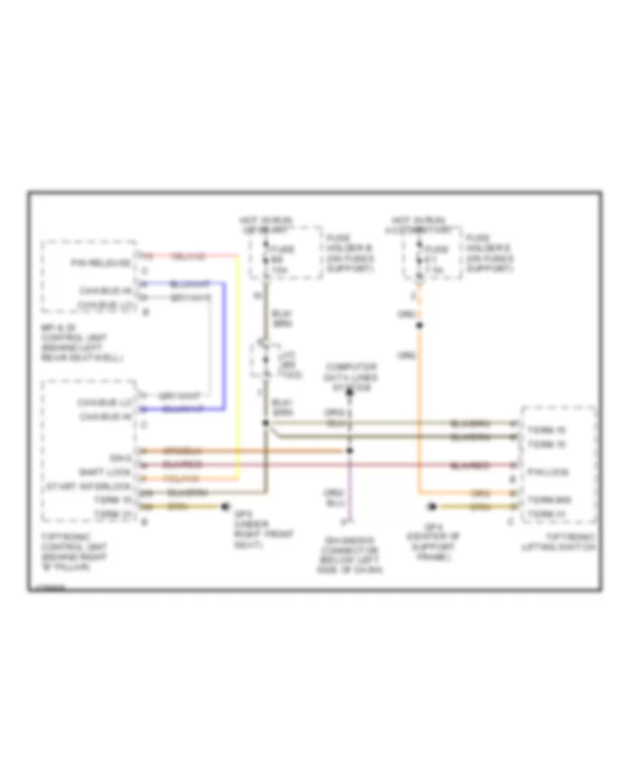
Shift Interlock Wiring Diagram, Early Production for Porsche 911 GT3 2004
List of elements for Shift Interlock Wiring Diagram, Early Production for Porsche 911 GT3 2004:
ANTI-LOCK BRAKESACTIVE BODYWORKSANTI-THEFTAIR CONDITIONINGCOOLING FANCRUISE CONTROLCOMPUTER DATA LINESENGINE PERFORMANCEELECTRONIC MUFFLERDEFOGGERSGROUND DISTRIBUTIONHORNEXTERIOR LIGHTSINSTRUMENT CLUSTERPOWER TOP/SUNROOFHEADLIGHTSMEMORY SYSTEMSPOWER DISTRIBUTIONINTERIOR LIGHTSPOWER DOOR LOCKSNAVIGATIONSHIFT INTERLOCKPOWER WINDOWSPOWER MIRRORSSTARTING/CHARGINGSUPPLEMENTAL RESTRAINTSRADIOTRUNK, TAILGATE, FUEL DOORTRANSMISSIONPOWER SEATSWIPER/WASHER