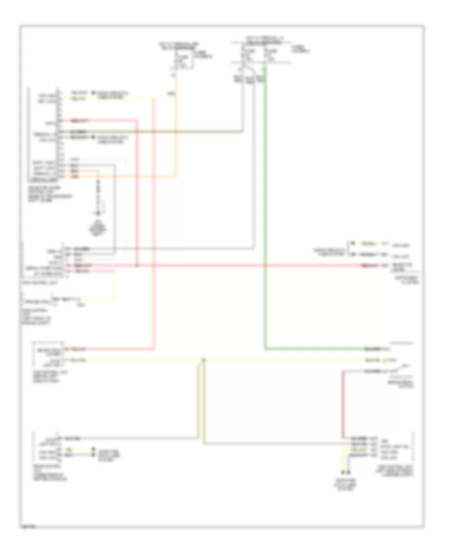
SHIFT INTERLOCK
Shift Interlock Wiring Diagram for Porsche 911 Turbo S 2011
List of elements for Shift Interlock Wiring Diagram for Porsche 911 Turbo S 2011:
- +bs
- Brake pedal switch
- Can high
- Can high can low
- Can low
- Computer data lines system
- Data
- Dme control unit (left front of engine compt)
- Fuse f4 10a
- Fuse f5 15a
- Fuse f9 7.5a
- Fuses holder b
- Fuses holder c
- Gnd
- Gp7 (under driver's seat)
- Hot w/ terminal 15 relay energized
- Hot w/ terminal 86s relay energized
- Instrument cluster
- Key lock
- Pas control unit (behind left side of dash)
- Pdk control unit
- Prk/neutral
- Psm control unit (left side of front luggage compt)
- Rear control unit (under rear of center console)
- Selector & locked
- Selector lever
- Selector lever control unit (base of transmission shift lever)
- Serial inter face
- Shift lock+
- Shift lock-
- St interlock
- Stop light sw
- Stop light sw a
- Suply
- Term 15
- Terminal 15
- Terminal 31
- Terminal 86s
- X021
 English