SHIFT INTERLOCK
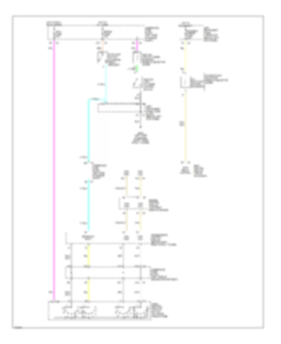
Shift Interlock Wiring Diagram for Saturn L300 2003
List of elements for Shift Interlock Wiring Diagram for Saturn L300 2003:
- A/t shiftlock actuator (base of selector lever)
- A/t shiftlock control solendoid
- A10
- A12
- B11
- B12
- Body control module (top of glove box)
- Brake fuse 15a
- Brake sw input
- Btsi relay control
- Btsi/bcm/ mirror fuse 10a
- Can high
- Can low
- E11
- Engine control module (top right rear of engine)
- F10
- F11
- G304 (left side of engine compt, near strut tower)
- Hot at all times
- Hot in accy, run & crank
- Hot in run & accy
- Ign 0 fuse 10a
- Ignition lock cylinder control switch
- Ignition lock cylinder solenoid (base of selector lever)
- Left instrument panel fuse block (behind left kick panel)
- Park/ neutral position switch (on trans- mission case)
- Stoplamp switch (on brake pedal bracket)
- Tan
- Transmission control module (behind right front strut tower)
- Underhood fuse block (left side of engine compartment)
- Underhood fuse block (left side of engine compt)
 Русский