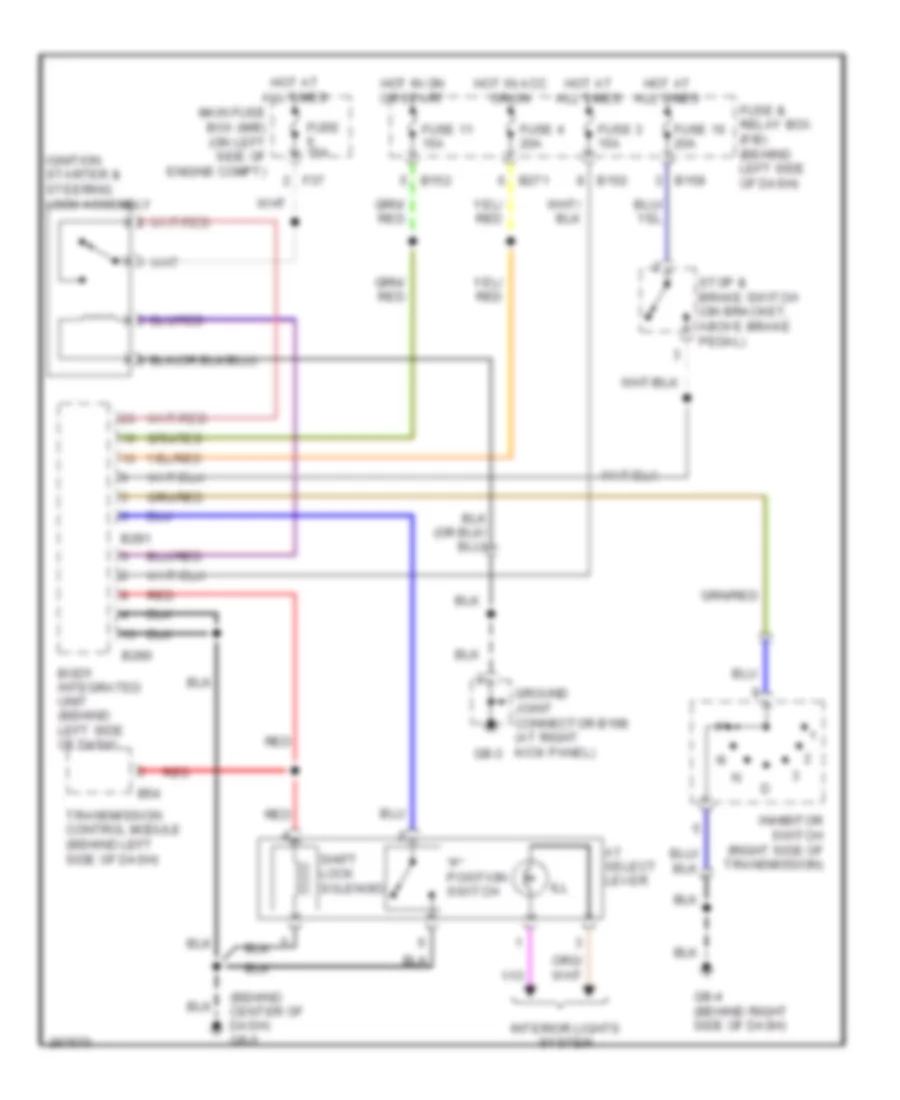
SHIFT INTERLOCK
Shift Interlock Wiring Diagram for Subaru Impreza WRX STi 2007
List of elements for Shift Interlock Wiring Diagram for Subaru Impreza WRX STi 2007:
- "p" position switch
- (behind center of dash) gb-5
- At select lever
- B152
- B158
- B271
- B280
- B281
- B54
- Body integrated unit (behind left side of dash)
- F37
- Fuse & relay box (f/b) (behind left side of dash)
- Fuse 11 15a
- Fuse 15a
- Fuse 16 20a
- Fuse 3 15a
- Fuse 4 20a
- Gb-3
- Gb-4 (behind right side of dash)
- Ground joint connector b198 (at right kick panel)
- Hot at all times
- Hot in acc or on
- Hot in on or start
- Ignition starter & steering lock assembly
- Ill
- Inhibitor switch (right side of transmission)
- Interior lights system
- Main fuse box (m/b) (on left side of engine compt)
- Red
- Shift lock solenoid
- Stop & brake switch (on bracket, above brake pedal)
- Transmission control module (behind left side of dash)
 English