SHIFT INTERLOCK
Park Brake Release Wiring Diagram for Subaru Outback Limited 2013

List of elements for Park Brake Release Wiring Diagram for Subaru Outback Limited 2013:
- (base of left "b" pillar) gb-10
- (right kick panel) gb-5
- B152
- B36 i1
- Body integrated unit (center of dash)
- Buzzer (epb)
- Ceiver & trans- can
- Clutch stroke sensor (m/t) (left side of dash)
- Combination meter
- Computer data lines system
- Drive circuit
- Driver circuit
- Epb control module (under rear seat)
- Epb control switch
- Epb on ind
- Epb warning light ind (c6 model)
- Fuse & relay box (f/b) (left kick panel)
- Fuse 19 7.5a
- Fuse 7 7.5a
- Hill hold switch
- Hot at all times
- Hot in on or start
- I102
- I102 r167
- I131
- I152
- I84
- Interior lights system
- Lock
- Main fuse box (m/b) (left side of engine compt)
- Micro computer
- Navigation unit
- Parking brake/ brake fluid level warning light ind
- Pnk
- R167
- R342
- R354
- Receiver
- Red
- Release
- Sbf-9 fuse 30a
- Vdc control module (right rear corner of engine compt)
- W/ navigation
- W/o navigation
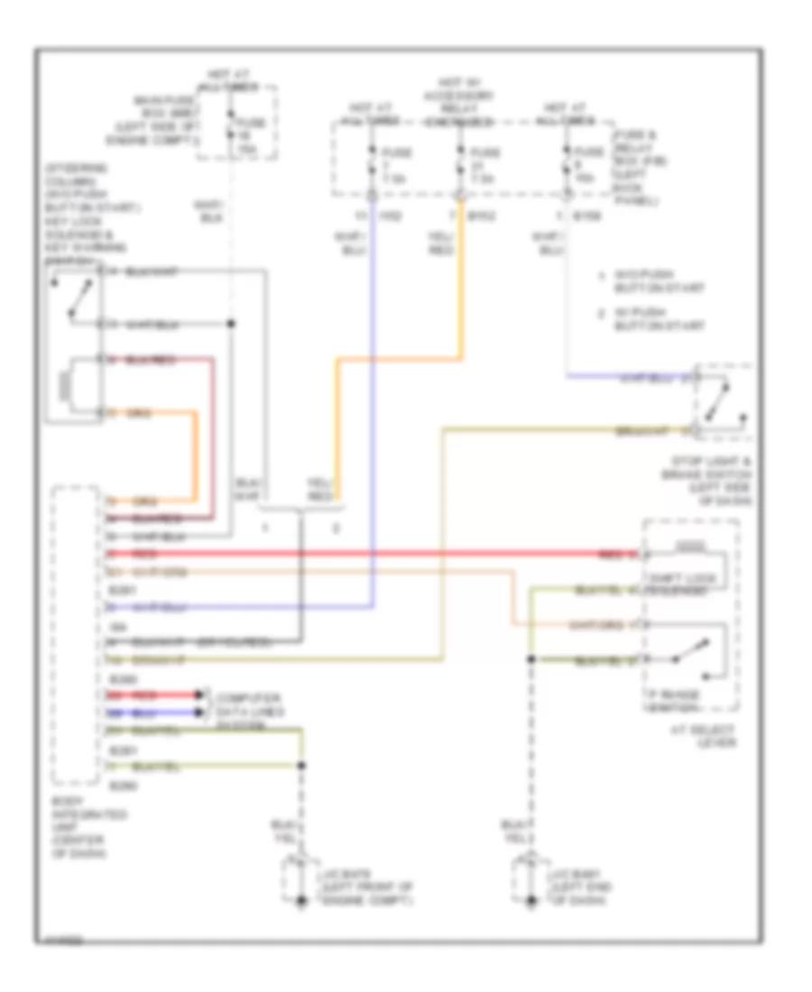
Shift Interlock Wiring Diagram for Subaru Outback Limited 2013
List of elements for Shift Interlock Wiring Diagram for Subaru Outback Limited 2013:
- (steering column) (w/o push button start) key lock solenoid & key warning switch
- At select lever
- B152
- B158
- B280
- B281
- Body integrated unit (center of dash)
- Button start
- Computer data lines system
- Fuse & relay box (f/b) (left kick panel)
- Fuse 15a
- Fuse 7.5a
- Hot at all times
- Hot w/ accessory relay energized
- I152
- I84
- J/c b479 (left front of engine compt)
- J/c b491 (left end of dash)
- Main fuse box (m/b) (left side of engine compt)
- P range switch
- Red
- Shift lock solenoid
- Stop light & brake switch (left side of dash)
- W/ push
- W/o push button start