
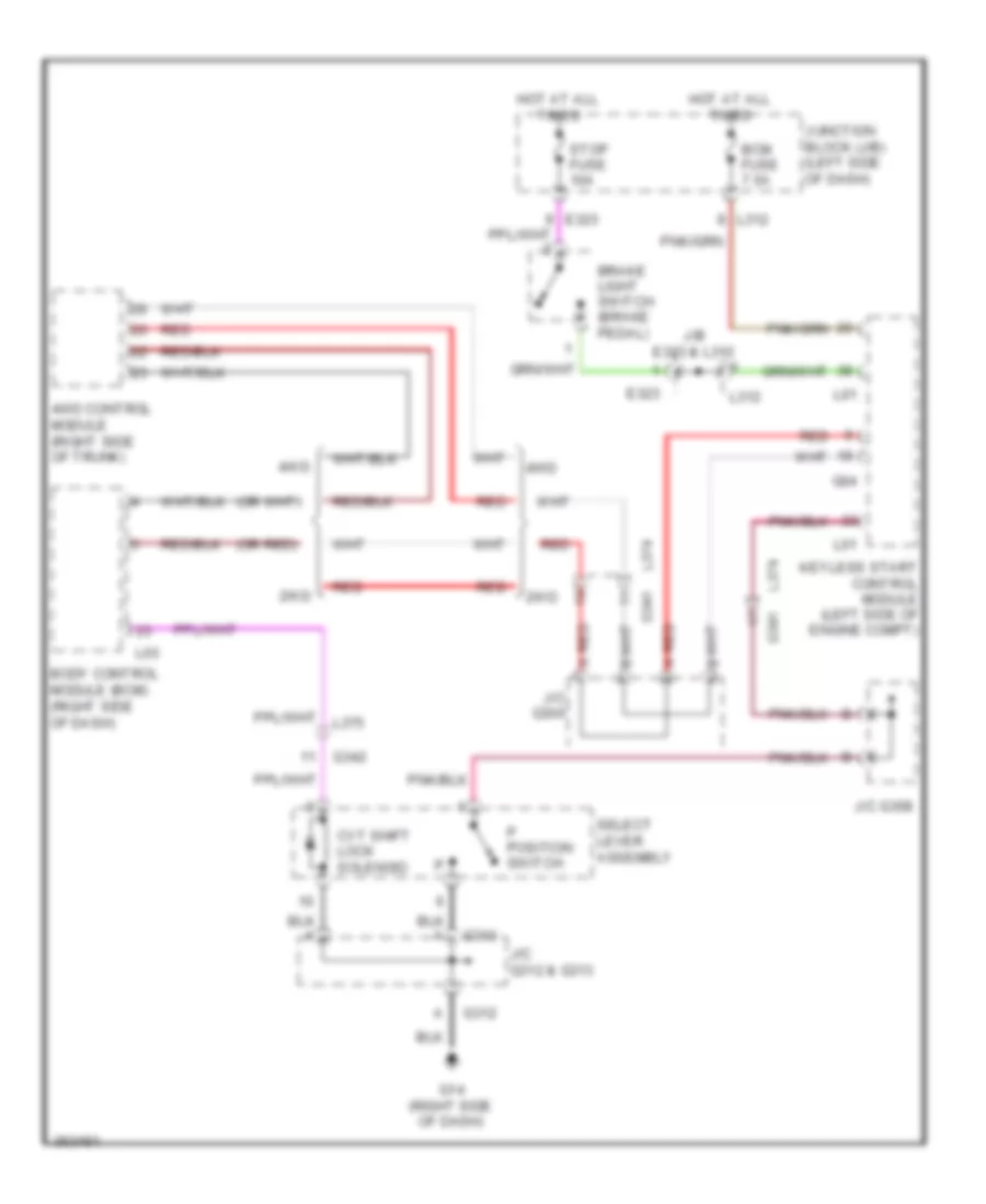
SHIFT INTERLOCK
Shift Interlock Wiring Diagram for Suzuki Kizashi SE 2012
List of elements for Shift Interlock Wiring Diagram for Suzuki Kizashi SE 2012:
AIR CONDITIONINGANTI-THEFTANTI-LOCK BRAKESBODY CONTROL MODULESCOMPUTER DATA LINESCRUISE CONTROLELECTRONIC POWER STEERINGDEFOGGERSEXTERIOR LIGHTSCOOLING FANENGINE PERFORMANCEGROUND DISTRIBUTIONHEADLIGHTSMEMORY SYSTEMSPOWER TOP/SUNROOFINTERIOR LIGHTSNAVIGATIONPOWER DISTRIBUTIONPOWER SEATSPOWER MIRRORSINSTRUMENT CLUSTERHORNPOWER WINDOWSPOWER DOOR LOCKSWARNING SYSTEMSTRUNK, TAILGATE, FUEL DOORRADIOSUPPLEMENTAL RESTRAINTSSTARTING/CHARGINGSHIFT INTERLOCKTRANSMISSIONWIPER/WASHER