
SHIFT INTERLOCK
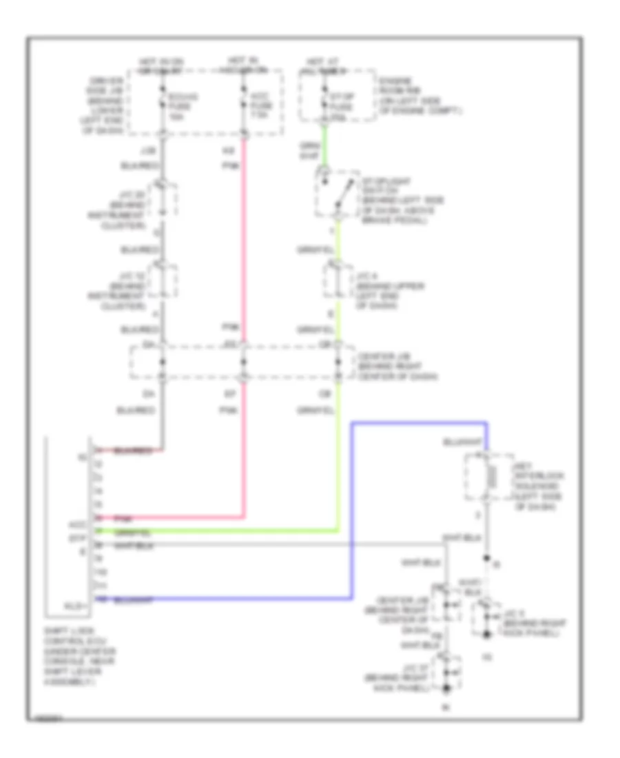
Shift Interlock Wiring Diagram for Toyota 4Runner Limited 2004
List of elements for Shift Interlock Wiring Diagram for Toyota 4Runner Limited 2004:
ANTI-LOCK BRAKESCRUISE CONTROLAIR CONDITIONINGANTI-THEFTBODY CONTROL MODULESCOMPUTER DATA LINESPASSIVE RESTRAINTSENGINE PERFORMANCEEXTERIOR LIGHTSELECTRONIC SUSPENSIONDEFOGGERSINTERIOR LIGHTSINSTRUMENT CLUSTERGROUND DISTRIBUTIONHEADLIGHTSHORNPOWER DOOR LOCKSPOWER WINDOWSPOWER TOP/SUNROOFPOWER DISTRIBUTIONRADIOSUPPLEMENTAL RESTRAINTSPOWER SEATSPOWER MIRRORSSHIFT INTERLOCKSTARTING/CHARGINGTRANSMISSIONWARNING SYSTEMSWIPER/WASHER