SHIFT INTERLOCK
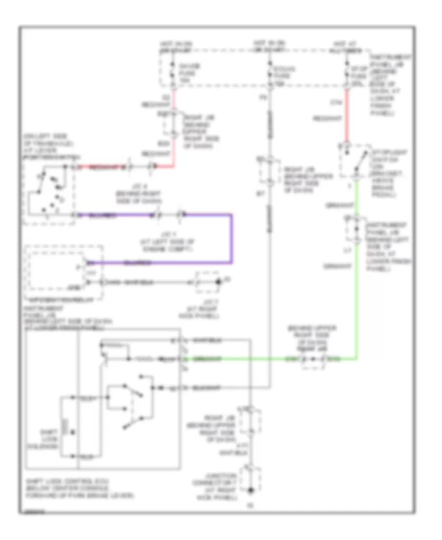
Shift Interlock Wiring Diagram for Toyota Corolla CE 2008
List of elements for Shift Interlock Wiring Diagram for Toyota Corolla CE 2008:
- (behind upper right side of dash) right j/b
- (on left side of transaxle) a/t lever position switch
- A16
- B20
- B22
- C10
- C13
- C14
- Ecu-ig fuse 10a
- Gauge fuse 10a
- Gnd
- H10
- Hot at all times
- Hot in on or start
- I11
- Instrument panel j/b (behind left side of dash, at lower finish panel)
- Integration relay
- J/c 1 (at left side of engine compt)
- J/c 4 (behind right side of dash)
- J/c 7 (at right kick panel)
- Junction connector 7 (at right kick panel)
- Right j/b (behind upper right side of dash)
- Shift lock control ecu (below center console, forward of park brake lever)
- Shift lock solenoid
- Sls+
- Sls-
- Stop fuse 15a
- Stoplight switch (on bracket, above brake pedal)
- Stp
 English