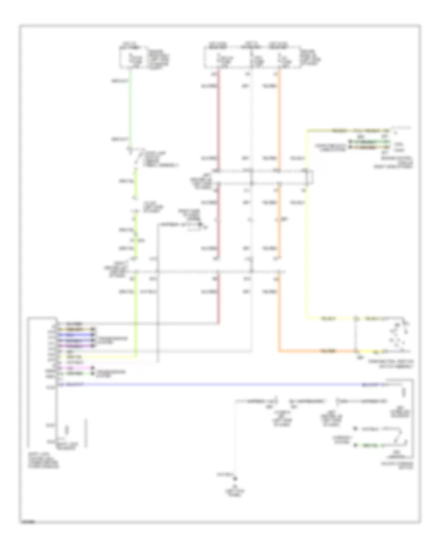
SHIFT INTERLOCK
Shift Interlock Wiring Diagram for Toyota FJ Cruiser 2013
List of elements for Shift Interlock Wiring Diagram for Toyota FJ Cruiser 2013:
- (right side of dash) j/c e52
- Acc
- Acc fuse 7.5a
- B12
- B15
- B47
- Be1
- Be3
- C11
- Canh
- Canl
- Computer data lines system
- D11
- D15
- Driver side j/b (left side of dash)
- E4 (left kick panel)
- E50
- E51
- E77
- Ea4
- Ecu-ig fuse 10a
- Ee1
- Engine control module (right side of dash)
- Engine room r/b 3 (left side of engine compt)
- Hot at all times
- Hot in on or acc
- Hot in on or start
- Ig1 fuse 15a
- J/c a27 (left side of dash)
- J/c e50 & e51 (left side of dash)
- J12
- J28
- Key interlock solenoid
- Key switch
- Kls+
- Left center j/b (left side of dash)
- M14
- Mt2
- Mt4
- Mtd
- Mtl
- N13
- Nssd
- Nssl
- Park/neutral position
- Right center j/b (center of dash)
- Shift lock control ecu (under center floor console)
- Sls+
- Sls- shift lock solenoid
- Stop fuse 10a
- Stop lamp switch (brake pedal assembly)
- Stp
- Switch assembly
- Transmissions system
- Unlock warning switch
- Warning system
 English