SHIFT INTERLOCK
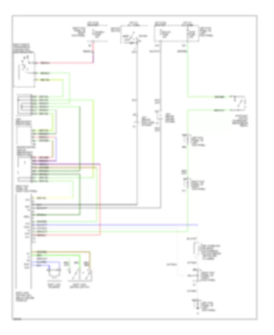
Shift Interlock Wiring Diagram for Toyota Land Cruiser 2007
List of elements for Shift Interlock Wiring Diagram for Toyota Land Cruiser 2007:
- (right side of transmission) park/neutral position switch
- Acc
- Alt
- At4
- C16
- C17
- C19
- C20
- D10
- D16
- D27
- D30
- D31
- D35
- E18
- E26
- Ecu-ig1 fuse 10a
- Engine control module (behind right side of dash)
- Gauge 2 fuse 10a
- Hot at all times
- Hot in on or start
- Ignition switch
- J/b 4 (behind center of dash)
- J/b 6 (behind right side of dash)
- J/b 7 (behind right side of dash)
- Key interlock solenoid (on steering column, behind ignition key cylinder)
- Kls+
- Left kick panel j/b (left kick panel)
- Lock
- Nssl
- Off
- P10
- P11
- P12
- P13
- P14
- Right kick panel j/b (right kick panel)
- Shift lock control ecu (below center console)
- Shift lock control switch
- Shift lock solenoid
- Sls+
- Sls-
- Start
- Stop fuse 15a
- Stoplight switch (on bracket, above brake pedal)
- Stp
 Русский