SHIFT INTERLOCK
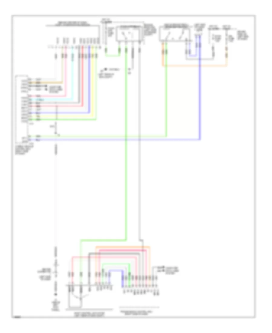
Shift Interlock Wiring Diagram for Toyota Prius 2004
List of elements for Shift Interlock Wiring Diagram for Toyota Prius 2004:
- (above brake pedal) stoplight switch
- (behind center of dash) shift lever position sensor
- (left end of dash) j/c 9
- (left rear of eng compt)
- A18
- A27
- Bma
- Canh
- Canl
- Center connector (left side of dash)
- Computer data lines system
- Driver side j/b (left end of dash)
- E14
- E2x1
- E2x2
- Engine room r/b (left side of engine compt)
- H14
- H15
- Hot at all times
- Hot w/ ign on
- Hybrid vehicle control ecu (right side of dash)
- Ign fuse 7.5a
- Ih (above left kick panel)
- Mgna
- Mpx1
- Mpx2
- Mua
- Mva
- Mwa
- Nca
- P con mtr fuse 30a
- P con mtr relay
- Pnk
- Re2
- Red
- Rvc
- Rz1
- Shift control actuator (left rear of eng compt)
- St1-
- Stop fuse 7.5a
- Stp
- Transmission control ecu (right side of dash)
- Vcx1
- Vcx2
- Vcx3
- Vcx4
- Vsx2
- Vsx3
- Vsx4
- Vxs1
- Vxs4
 English