SHIFT INTERLOCK
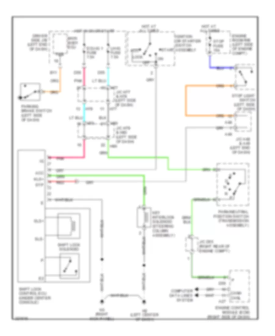
Shift Interlock Wiring Diagram for Toyota Sequoia Limited 2010
List of elements for Shift Interlock Wiring Diagram for Toyota Sequoia Limited 2010:
- A27
- A48
- A49
- Acc
- B11
- Canh
- Canl
- Computer data lines system
- D55
- D56
- Driver side j/b (left end of dash)
- Ecu-ig 1 fuse 7.5a
- Engine control module (ecm) (right side of dash)
- Engine room r/b (left side of engine compt)
- H2 (left center of dash)
- H3 (right kick panel)
- H77
- H78
- H79
- H80
- Hot at all times
- Hot in on or start
- Ignition or starter switch assembly
- J/c a48 & a49 (left end of dash)
- J/c d55 (right rear of engine compt)
- J/c h77 & h78 (left side of dash)
- J/c h79 & h80 (left side of dash)
- Key interlock solenoid (steering column assembly)
- Kls+
- Lh-ig fuse 7.5a
- Lock
- Main body ecu
- Off
- Park/neutral position switch (transmission assembly)
- Parking brake switch (left side of dash)
- Pkb
- Pnk
- Red
- Shift lock control ecu (under center console)
- Shift lock solenoid
- Sls+
- Sls-
- Start
- Stop fuse 15a
- Stop light switch (left side of dash)
- Stp
 English