
SHIFT INTERLOCK
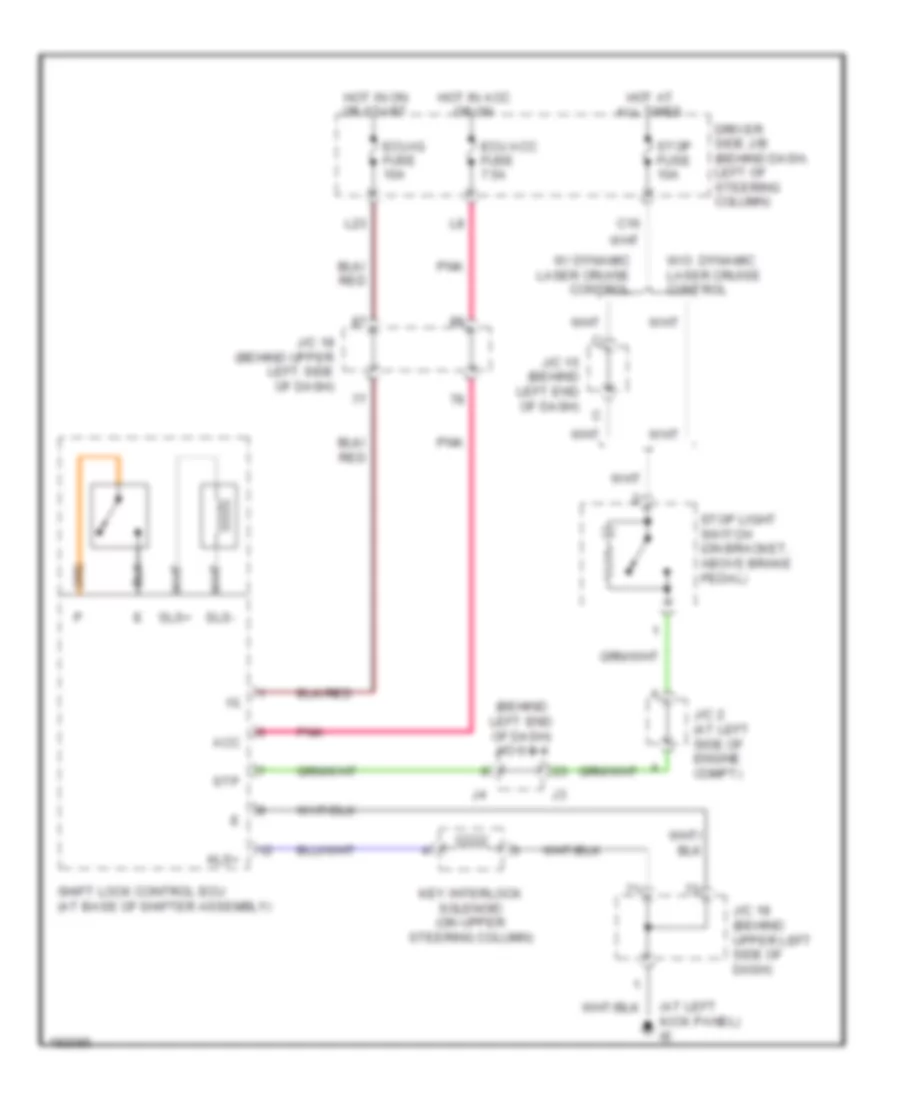
Shift Interlock Wiring Diagram for Toyota Sienna CE 2005
List of elements for Shift Interlock Wiring Diagram for Toyota Sienna CE 2005:
ANTI-LOCK BRAKESCOOLING FANANTI-THEFTCRUISE CONTROLAIR CONDITIONINGCOMPUTER DATA LINESBODY CONTROL MODULESDEFOGGERSENGINE PERFORMANCEHEADLIGHTSEXTERIOR LIGHTSHORNINTERIOR LIGHTSINSTRUMENT CLUSTERGROUND DISTRIBUTIONNAVIGATIONPOWER WINDOWSPOWER DISTRIBUTIONPOWER TOP/SUNROOFSHIFT INTERLOCKPOWER MIRRORSPOWER SEATSRADIOTRANSMISSIONSTARTING/CHARGINGSUPPLEMENTAL RESTRAINTSTRUNK, TAILGATE, FUEL DOORWARNING SYSTEMSWIPER/WASHER