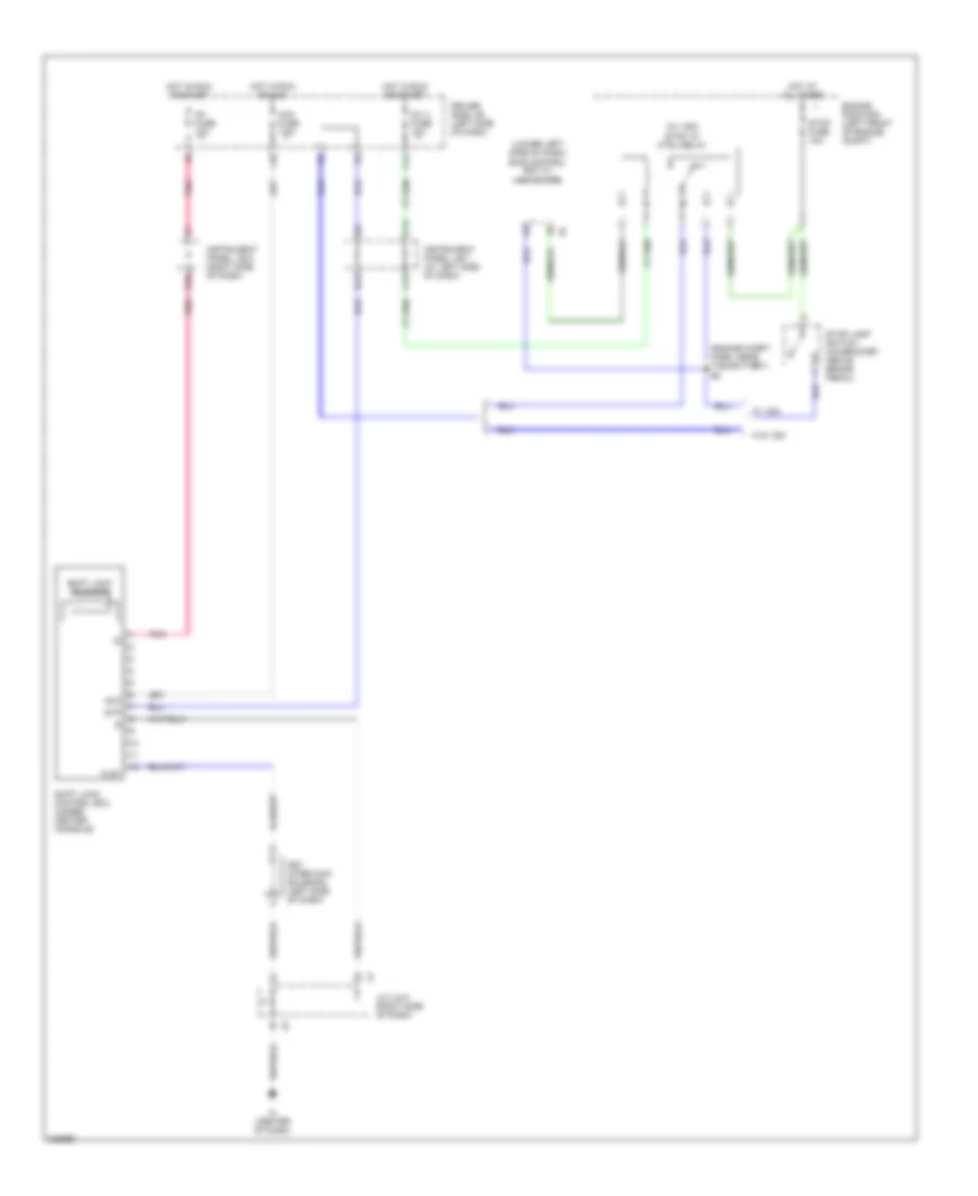
SHIFT INTERLOCK
Shift Interlock Wiring Diagram for Toyota Tacoma 2006
List of elements for Shift Interlock Wiring Diagram for Toyota Tacoma 2006:
- (engine compt harn, near the battery) e2
- (lower left side of dash) skid control ecu w/ actuator
- (w/ vsc) stop lp ctrl relay
- Acc
- Acc fuse 7.5a
- B14
- C12
- C13
- C14
- Driver side j/b (left side of dash)
- E10
- Engine room r/b (left front of engine compt)
- Hot at all times
- Hot in run or acc
- Hot in run or start
- Ic (center of dash)
- Ig1 2 fuse 10a
- Ig1 fuse 10a
- Instrument panel j/b 1 (at left side of dash)
- Instrument panel j/b 2 (right side of dash)
- J/c 4 & 5 (right side of dash)
- J10
- Key interlock solenoid (left side of dash)
- Kls+
- Pnk
- Shift lock control ecu (under center console)
- Shift lock solenoid
- Stop fuse 10a
- Stop lamp switch (on bracket, above brake pedal)
- Stp
- W/ vsc
- W/o vsc
 English