SHIFT INTERLOCK
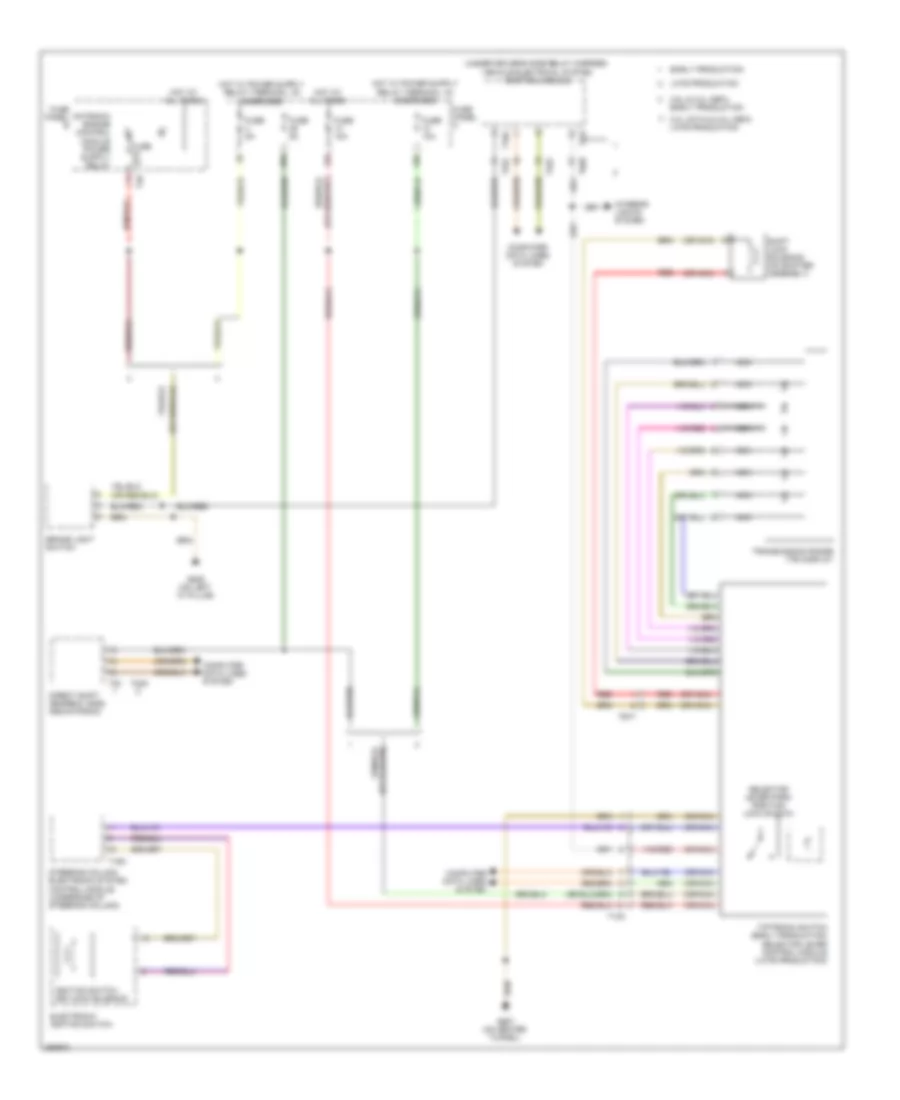
Electronic Parking Brake Wiring Diagram, Early Production for Volkswagen CC VR6 4Motion 2010

List of elements for Electronic Parking Brake Wiring Diagram, Early Production for Volkswagen CC VR6 4Motion 2010:
Electronic Parking Brake Wiring Diagram, Late Production for Volkswagen CC VR6 4Motion 2010
List of elements for Electronic Parking Brake Wiring Diagram, Late Production for Volkswagen CC VR6 4Motion 2010:
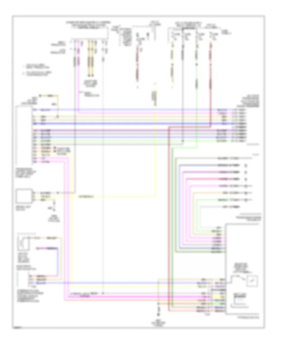
Shift Interlock Wiring Diagram, with Direct Shift for Volkswagen CC VR6 4Motion 2010
List of elements for Shift Interlock Wiring Diagram, with Direct Shift for Volkswagen CC VR6 4Motion 2010:
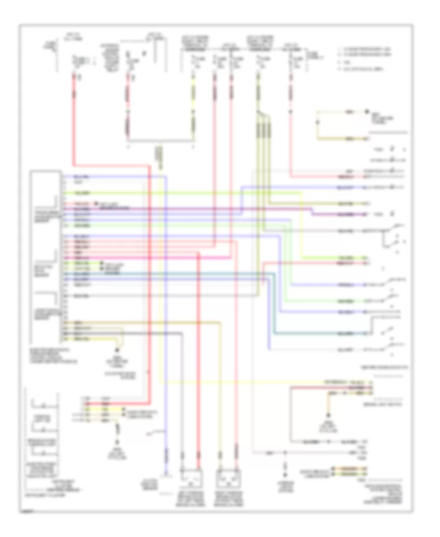
Shift Interlock Wiring Diagram, without Direct Shift for Volkswagen CC VR6 4Motion 2010
List of elements for Shift Interlock Wiring Diagram, without Direct Shift for Volkswagen CC VR6 4Motion 2010: