
SHIFT INTERLOCK
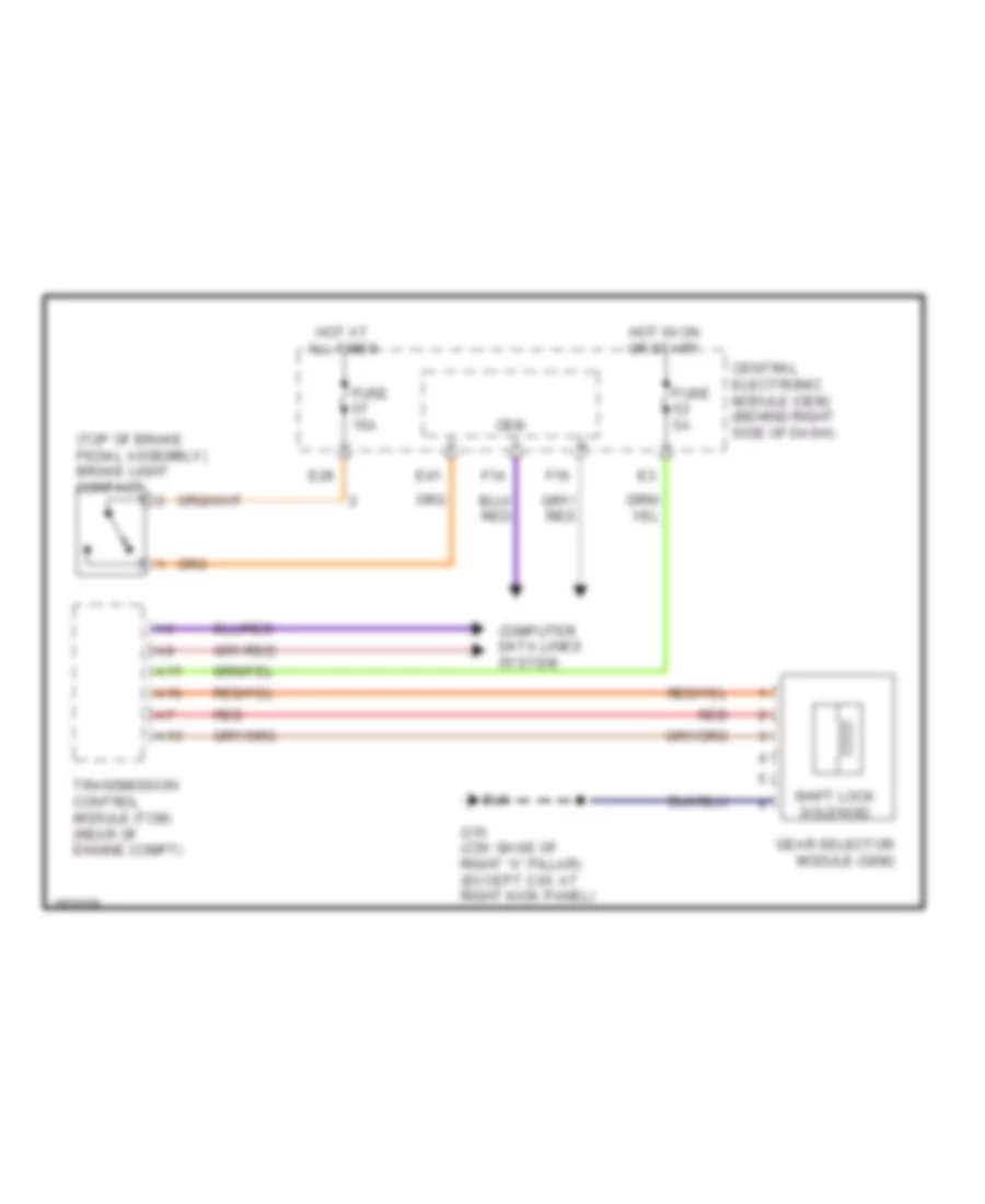
Shift Interlock Wiring Diagram for Volvo C30 T-5 2008
List of elements for Shift Interlock Wiring Diagram for Volvo C30 T-5 2008:
ANTI-LOCK BRAKESAIR CONDITIONINGANTI-THEFTCOOLING FANBODY CONTROL MODULESCOMPUTER DATA LINESELECTRONIC POWER STEERINGDEFOGGERSENGINE PERFORMANCEEXTERIOR LIGHTSCRUISE CONTROLINTERIOR LIGHTSGROUND DISTRIBUTIONINSTRUMENT CLUSTERHEADLIGHTSMEMORY SYSTEMSHORNPOWER DOOR LOCKSPOWER DISTRIBUTIONPOWER TOP/SUNROOFPOWER SEATSPOWER WINDOWSPOWER MIRRORSNAVIGATIONRADIOSHIFT INTERLOCKSTARTING/CHARGINGWARNING SYSTEMSSUPPLEMENTAL RESTRAINTSTRANSMISSIONTRUNK, TAILGATE, FUEL DOORWIPER/WASHER