
SHIFT INTERLOCK
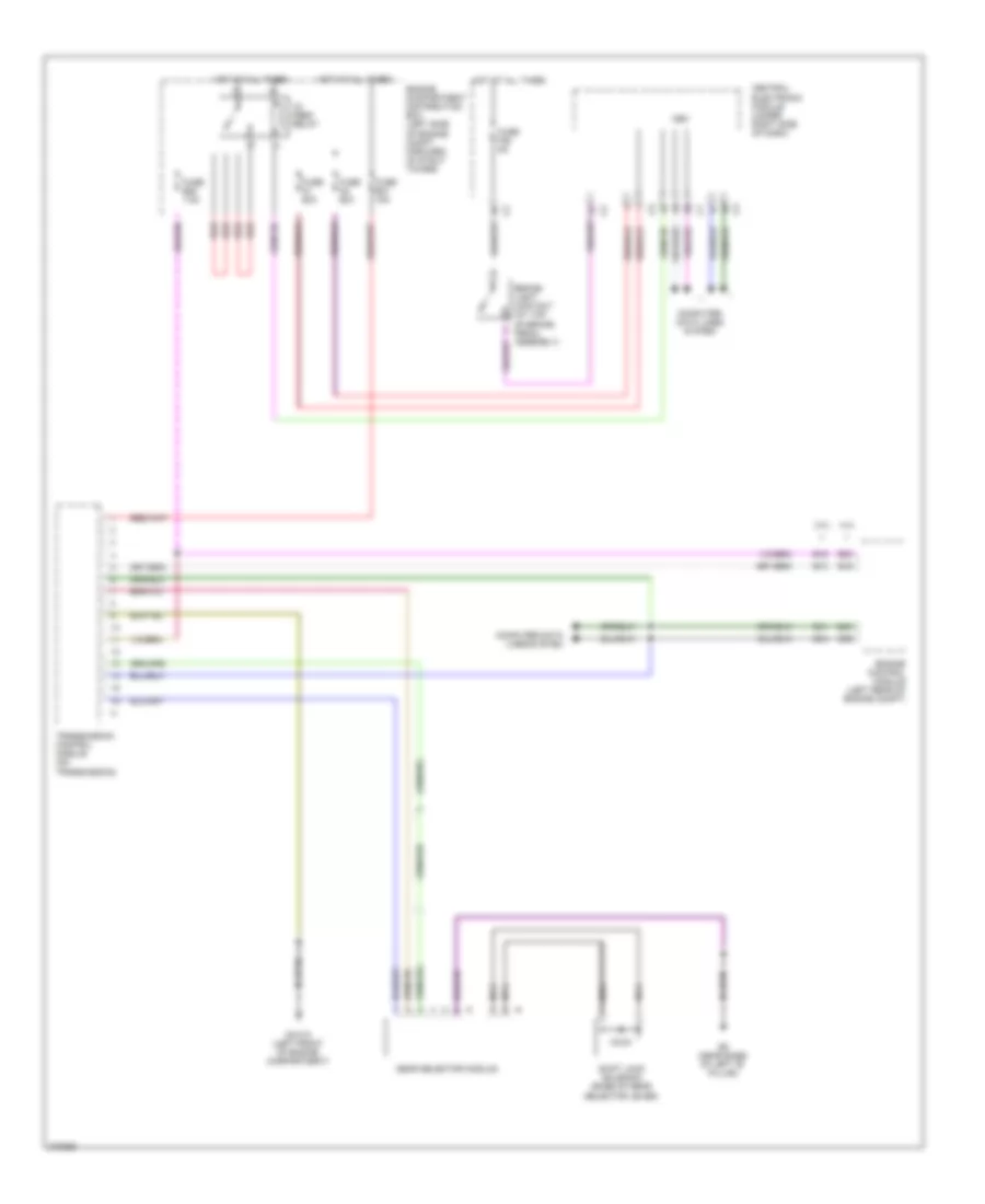
Shift Interlock Wiring Diagram for Volvo S80 2007
List of elements for Shift Interlock Wiring Diagram for Volvo S80 2007:
ANTI-LOCK BRAKESCOMPUTER DATA LINESANTI-THEFTAIR CONDITIONINGCOOLING FANBODY CONTROL MODULESCRUISE CONTROLDEFOGGERSELECTRONIC POWER STEERINGENGINE PERFORMANCEEXTERIOR LIGHTSGROUND DISTRIBUTIONHORNELECTRONIC SUSPENSIONHEADLIGHTSINSTRUMENT CLUSTERPOWER DOOR LOCKSNAVIGATIONINTERIOR LIGHTSPOWER TOP/SUNROOFMEMORY SYSTEMSRADIOPOWER WINDOWSPOWER DISTRIBUTIONSTARTING/CHARGINGPOWER SEATSPOWER MIRRORSSHIFT INTERLOCKSUPPLEMENTAL RESTRAINTSTRANSMISSIONTRUNK, TAILGATE, FUEL DOORWARNING SYSTEMSWIPER/WASHER