SHIFT INTERLOCK
Shift Interlock Wiring Diagram for Volvo S80 T-6 2004
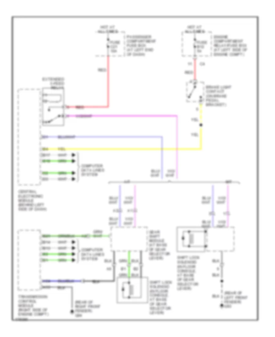
List of elements for Shift Interlock Wiring Diagram for Volvo S80 T-6 2004:
- (in floor console, at base of gear selector lever)
- (rear of left front fender) g93
- (rear of right front fender) g94
- A/t
- A53
- A54
- B13
- B14
- B17
- B18
- B21
- Brake light contact (on brake pedal bracket)
- Central electronic module (behind left side of dash)
- Computer data lines system
- Engine compartment relay/fuse box (at left side of engine compt)
- Extended x-feed relay
- Fuse b12 5a
- Fuse c21 10a
- Gear shift module (at base of gear selector lever)
- Hot at all times
- M/t
- Passenger compartment fuse box (at left end of dash)
- Red
- Shift lock solenoid
- Shift lock solenoid (in floor console, at base of gear selector lever)
- Transmission control module (right side of engine compt)
 English