SHIFT INTERLOCK
Reverse Lockout Wiring Diagram for Volvo V50 T-5 R-Design 2011

List of elements for Reverse Lockout Wiring Diagram for Volvo V50 T-5 R-Design 2011:
- Central electronic module (cem) (behind right side of dash)
- Engine compartment distribution box (left side of engine compt)
- Fuse 60a
- G10 (base of right "a" pillar)
- Hot at all times
- Reverse interlock solenoid (at base of shift lever assembly)
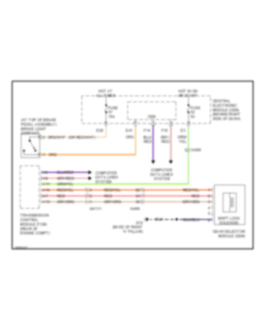
Shift Interlock Wiring Diagram for Volvo V50 T-5 R-Design 2011
List of elements for Shift Interlock Wiring Diagram for Volvo V50 T-5 R-Design 2011:
- (at top of brake pedal assembly) brake light contact
- 64/111
- 64/90
- A11
- A13
- A16
- Cem
- Central electronic module (cem) (behind right side of dash)
- Computer data lines system
- E28
- E41
- F14
- F16
- Fuse 15a
- Fuse 5a
- G10 (base of right "a" pillar)
- Gear selector module (gsm)
- Hot at all times
- Hot in on or start
- Red
- Shift lock solenoid
- Transmission control module (tcm) (rear of engine compt)