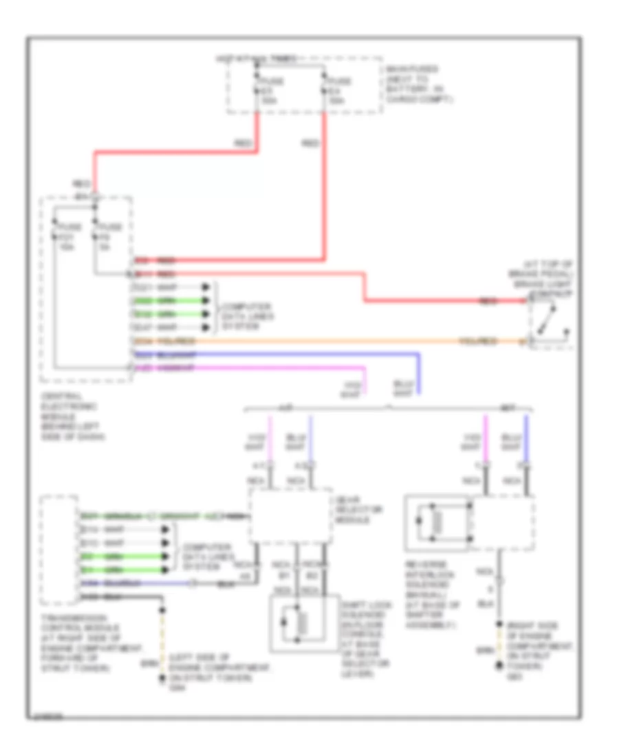
AUTOMOTIVE ELECTRICIANS PORTAL

SHIFT INTERLOCK – Volvo V70 2005 – SYSTEM WIRING DIAGRAMS

SHIFT INTERLOCK

Shift Interlock Wiring Diagram for Volvo V70 2005

Shift Interlock Wiring Diagram for Volvo V70 2005 https://portal-diagnostov.com/license.html
https://portal-diagnostov.com/license.html Automotive Electricians Portal FZCO Automotive Electricians Portal FZCO
Get access to all wiring diagrams of the carDownload PDF file

List of elements for Shift Interlock Wiring Diagram for Volvo V70 2005:

  • (at top of brake pedal) brake light contact
  • (left side of engine compartment, on strut tower) g94
  • (right side of engine compartment, on strut tower) g93
  • A/t
  • A25
  • A53
  • A54
  • B11
  • B13
  • B14
  • B21
  • C21
  • C22
  • C34
  • Central electronic module (behind left side of dash)
  • Computer data lines system
  • D23
  • D32
  • D47
  • Fuse e4 50a
  • Fuse e5 50a
  • Fuse f21 10a
  • Fuse f9 5a
  • Gear selector module
  • Hot at all times
  • M/t
  • Main fuses (next to battery, in cargo compt)
  • Nca
  • Red
  • Reverse interlock solenoid (manual) (at base of shifter assembly)
  • Shift lock solenoid (in floor console, at base of gear selector lever)
  • Transmission control module (at right side of engine compartment, forward of strut tower)