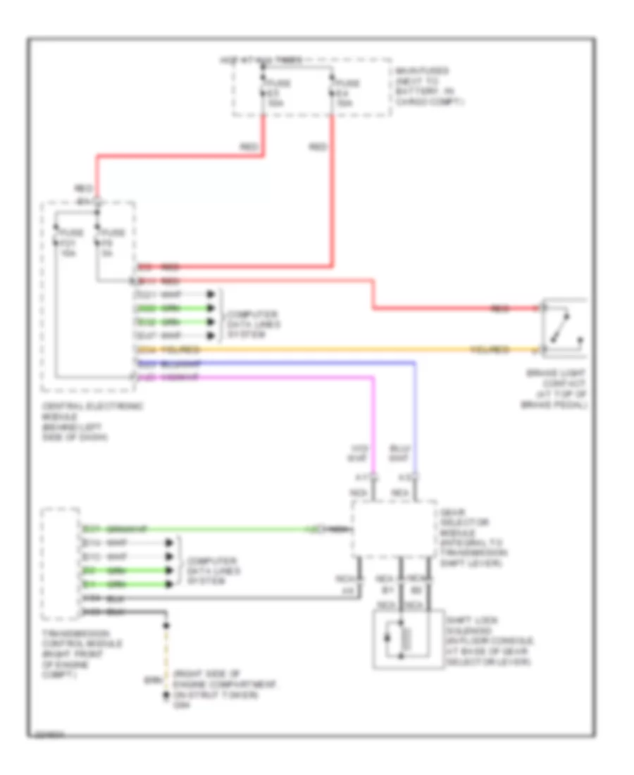
AUTOMOTIVE ELECTRICIANS PORTAL

SHIFT INTERLOCK – Volvo XC90 2010 – SYSTEM WIRING DIAGRAMS

SHIFT INTERLOCK

Shift Interlock Wiring Diagram for Volvo XC90 2010

Shift Interlock Wiring Diagram for Volvo XC90 2010 https://portal-diagnostov.com/license.html
https://portal-diagnostov.com/license.html Automotive Electricians Portal FZCO Automotive Electricians Portal FZCO
Nabavite Pristup svim shemama ožičenja automobilaDownload PDF file

List of elements for Shift Interlock Wiring Diagram for Volvo XC90 2010:

  • (right side of engine compartment, on strut tower) g94
  • A25
  • A53
  • A54
  • B11
  • B13
  • B14
  • B21
  • Brake light contact (at top of brake pedal)
  • C21
  • C22
  • C34
  • Central electronic module (behind left side of dash)
  • Computer data lines system
  • D23
  • D32
  • D47
  • Fuse e4 50a
  • Fuse e5 50a
  • Fuse f21 10a
  • Fuse f9 5a
  • Gear selector module (integral to transmission shift lever)
  • Hot at all times
  • Main fuses (next to battery, in cargo compt)
  • Nca
  • Red
  • Shift lock solenoid (in floor console, at base of gear selector lever)
  • Transmission control module (right front of engine compt)