
SHIFT INTERLOCK
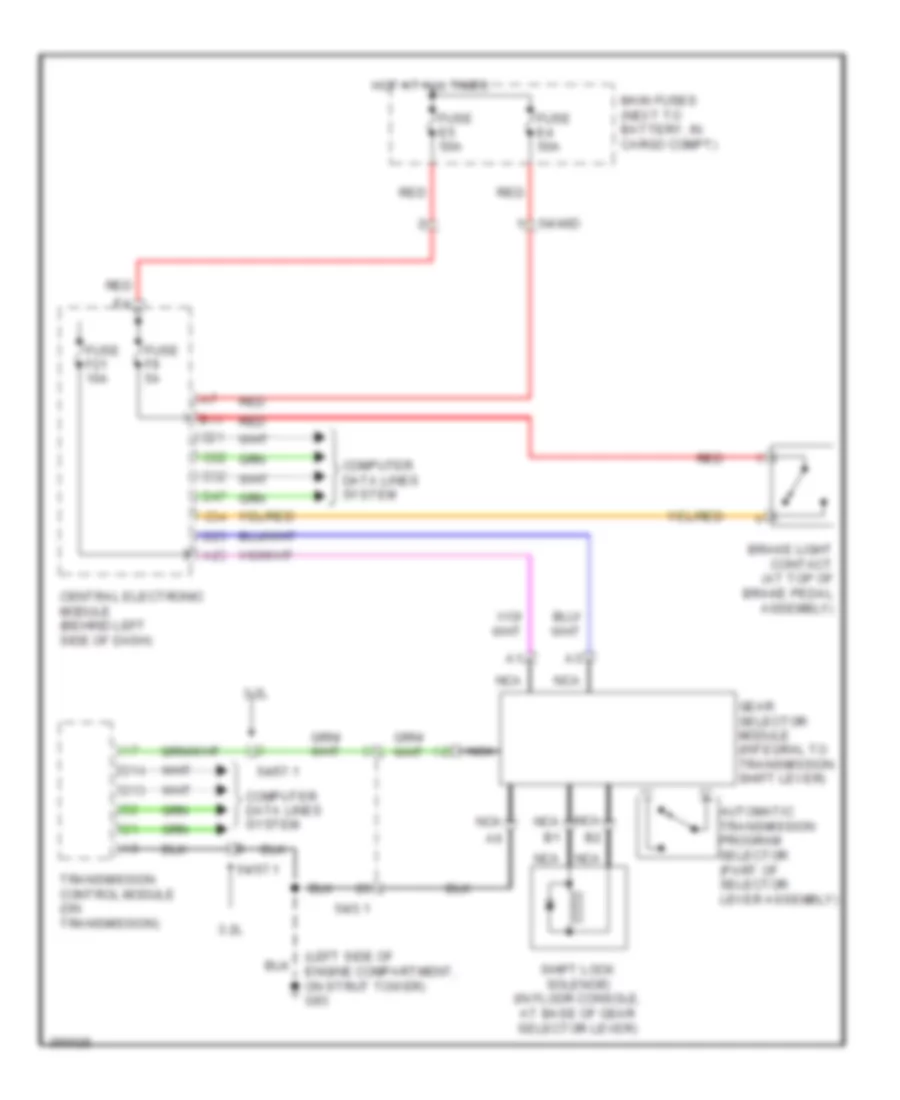
Shift Interlock Wiring Diagram for Volvo XC90 2011
List of elements for Shift Interlock Wiring Diagram for Volvo XC90 2011:
AIR CONDITIONINGANTI-LOCK BRAKESANTI-THEFTBODY CONTROL MODULESCOMPUTER DATA LINESCOOLING FANCRUISE CONTROLDEFOGGERSELECTRONIC POWER STEERINGENGINE PERFORMANCEEXTERIOR LIGHTSGROUND DISTRIBUTIONHEADLIGHTSHORNINSTRUMENT CLUSTERINTERIOR LIGHTSMEMORY SYSTEMSNAVIGATIONPOWER DISTRIBUTIONPOWER DOOR LOCKSPOWER SEATSPOWER TOP/SUNROOFPOWER WINDOWSRADIOSHIFT INTERLOCKSTARTING/CHARGINGSUPPLEMENTAL RESTRAINTSTRANSMISSIONWARNING SYSTEMSWIPER/WASHER