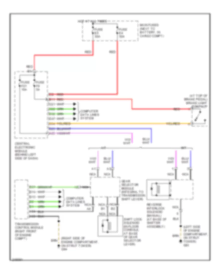
SHIFT INTERLOCK
Shift Interlock Wiring Diagram for Volvo XC90 R-Design 2009
List of elements for Shift Interlock Wiring Diagram for Volvo XC90 R-Design 2009:
- (at top of brake pedal) brake light contact
- (left side of engine compartment, on strut tower) g93
- (right side of engine compartment, on strut tower) g94
- A/t
- A25
- A53
- A54
- B11
- B13
- B14
- B21
- C21
- C22
- C34
- Central electronic module (behind left side of dash)
- Computer data lines system
- D23
- D32
- D47
- Fuse e4 50a
- Fuse e5 50a
- Fuse f21 10a
- Fuse f9 5a
- Gear selector module (integral to transmission shift lever)
- Hot at all times
- M/t
- Main fuses (next to battery, in cargo compt)
- Nca
- Red
- Reverse interlock solenoid (manual) (at base of shifter assembly)
- Shift lock solenoid (in floor console, at base of gear selector lever)
- Transmission control module (right front of engine compt)
 Русский