
SHIFT INTERLOCKS
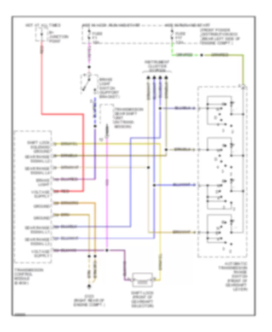
Shift Interlock Wiring Diagram for BMW 740i 1994
List of elements for Shift Interlock Wiring Diagram for BMW 740i 1994:
ANTI-LOCK BRAKESAIR CONDITIONINGANTI-THEFTCOMPUTER DATA LINESBODY COMPUTERCRUISE CONTROLDEFOGGERSELECTRONIC SUSPENSIONEXTERIOR LIGHTSCOOLING FANHORNINSTRUMENT CLUSTERGROUND DISTRIBUTIONHEADLIGHTSENGINE PERFORMANCEINTERIOR LIGHTSPOWER DISTRIBUTIONMEMORY SYSTEMSPOWER DOOR LOCKSPOWER MIRRORSPOWER TOP/SUNROOFPOWER WINDOWSSUPPLEMENTAL RESTRAINTSSTARTING/CHARGINGTRANSMISSIONSHIFT INTERLOCKSWARNING SYSTEMSTRUNK, TAILGATE, FUEL DOORRADIOWIPER/WASHER