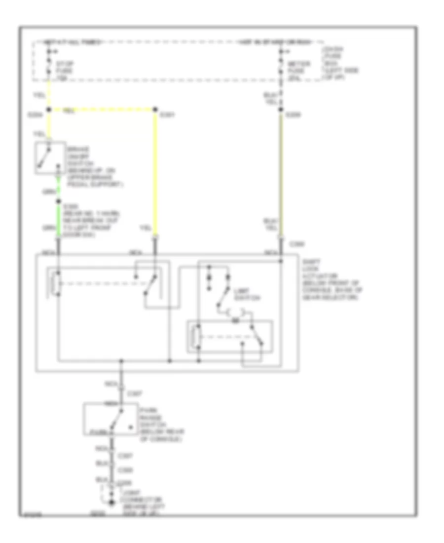
AUTOMOTIVE ELECTRICIANS PORTAL

SHIFT INTERLOCKS – Ford Aspire SE 1995 – SYSTEM WIRING DIAGRAMS

SHIFT INTERLOCKS

Shift Interlock Wiring Diagram for Ford Aspire SE 1995

Shift Interlock Wiring Diagram for Ford Aspire SE 1995 https://portal-diagnostov.com/license.html
https://portal-diagnostov.com/license.html Automotive Electricians Portal FZCO Automotive Electricians Portal FZCO
Obtenga acceso a todos los diagramas de cableado del cocheDownload PDF file

List of elements for Shift Interlock Wiring Diagram for Ford Aspire SE 1995:

  • Brake on/off switch (behind i/p, on upper brake pedal support)
  • C206
  • C300
  • C307
  • Dash fuse box (left side of i/p)
  • G202
  • Hot at all times
  • Hot in start or run
  • Joint connector (behind left side of i/p)
  • Limit switch
  • Meter fuse 15a
  • Nca
  • Park
  • Park range switch (below rear of console)
  • S204
  • S209
  • S300 (rear no. 1 harn, near break out to left front door sw)
  • S301
  • Shift lock actuator (below front of console, base of gear selector)
  • Stop fuse 15a