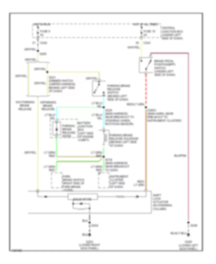
SHIFT INTERLOCKS
Shift Interlock Wiring Diagram for Ford Expedition 2001
List of elements for Shift Interlock Wiring Diagram for Ford Expedition 2001:
- Battery junction box (left side of engine compt)
- Brake pedal position(bpp) switch (under left side of dash)
- C242
- C243
- Central junction box (under left side of dash)
- Fuse 15 5a
- Fuse 6 5a
- G200 (lower left kick panel)
- G203 (lower right kick panel)
- Hot at all times
- Hot in run
- Instrument cluster (left side of dash)
- Park brake switch (right side of park brake lever)
- Parking brake release diode
- Parking brake release solenoid (behind left side of dash)
- Parking brake release switch (behind left side of dash)
- S2003 (main harn, near breakout to instrument cluster)
- S204
- S208
- S265
- Shift lock actuator (in steering column)
- Solid state
- To g200)
- W/o parking brake release
- W/parking brake release
 English