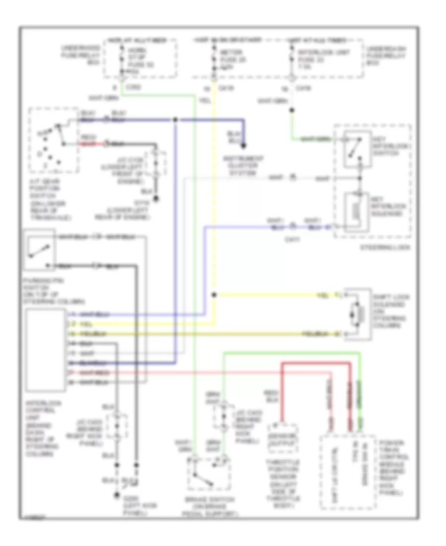
SHIFT INTERLOCKS
Shift Interlock Wiring Diagram for Honda CR-V EX 1999
List of elements for Shift Interlock Wiring Diagram for Honda CR-V EX 1999:
- (behind dash, right of steering column)
- (on left side of throttle body)
- (on lower rear of transaxle)
- A/t gear position switch
- A28
- A32
- Brake sw in
- Brake switch (on brake pedal support)
- C27
- C352
- C411
- C418
- C419
- G114 (lower left rear of engine)
- G200 (left kick panel)
- Horn, stop fuse 52 15a
- Hot at all times
- Hot in on or start
- Instrument cluster system
- Interlock control unit
- Interlock unit fuse 33 7.5a
- J/c c136 (lower left front of engine)
- J/c c433 (behind right kick panel)
- Key interlock solenoid
- Key interlock switch
- Meter fuse 25 7.5a
- N d
- Parking pin switch (on top of steering column)
- Power- train control module (behind right kick panel)
- Sensor output
- Shft lk cir ctrl
- Shift lock solenoid (on steering column)
- Steering lock
- Throttle position sensor
- Tps in
- Underdash fuse/relay box
- Underhood fuse/relay box
 English