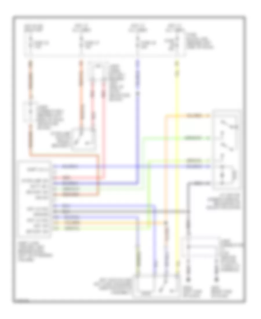
SHIFT INTERLOCKS
Shift Interlock Wiring Diagram for Infiniti Q45 1998
List of elements for Shift Interlock Wiring Diagram for Infiniti Q45 1998:
- 18b
- A/t device (under console, near base of selector lever)
- Batt (b+)
- Detent sw
- Fuse 10a
- Fuse 26 20a
- Fuse 32 7.5a
- Fuse 37 15a
- Fuse block (j/b) (behind left side of dash)
- G201 (right end of dash)
- G202 (left end of dash)
- Ground
- Hot at all times
- Hot in on or start
- Ign sw
- Joint conn- ector 1 (behind left side of dash, near fuse block)
- Joint connector (top center of dash, taped to harness)
- Joint connector 3 (behind left side of dash, near fuse block)
- Key lk sol
- Key sw
- Key switch and key lock solenoid (ignition switch assembly)
- Red
- Shift lk (+)
- Shift lock control unit (behind dash, left of steering column)
- Stoplamp sw
- Stoplamp switch (pedal bracket)
 English