SHIFT INTERLOCKS
Shift Interlock Wiring Diagram, Early Production for Isuzu Rodeo LS 1995

List of elements for Shift Interlock Wiring Diagram, Early Production for Isuzu Rodeo LS 1995:
- (below shift lever cover)
- (not used)
- Battery
- Brake input
- Brake light switch (on brake pedal support)
- C264
- C270
- Charge sig
- Dash fuse box (left side of i/p)
- Fuse 10a
- Fuse/ relay box (right side of engine compartment)
- G200 (left side kick panel)
- Ground
- Hot at all times
- Hot in on or start
- Ignition
- Park input
- Parking switch (below shift lever cover)
- Red
- Ref signal
- Safety lock control unit (below shift lever cover)
- Shift lock solenoid
- Solenoid control
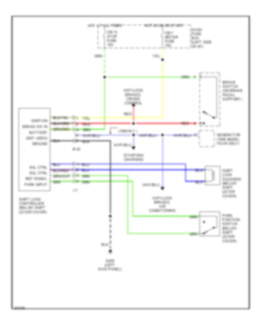
Shift Interlock Wiring Diagram, Late Production for Isuzu Rodeo LS 1995
List of elements for Shift Interlock Wiring Diagram, Late Production for Isuzu Rodeo LS 1995:
- (1996 m.y.)
- (not used)
- Anti-lock brakes, air conditioning
- Anti-lock brakes, cruise control
- B-32
- Battery
- Brake sw in
- Brake switch (on brake pedal support)
- Cb-13 stop fuse 15a
- Cb-7 meter fuse 15a
- Dash fuse box (left side of i/p)
- G200 (left kick panel)
- Generator (1996 model year only)
- Ground
- Hot at all times
- Hot in on or start
- Ignition
- J-1
- Park input
- Park position switch (below shift lever cover)
- Red
- Ref signal
- Shift lock controller (below shift lever cover)
- Shift lock solenoid (below shift lever cover)
- Sol ctrl
- Starting/ charging