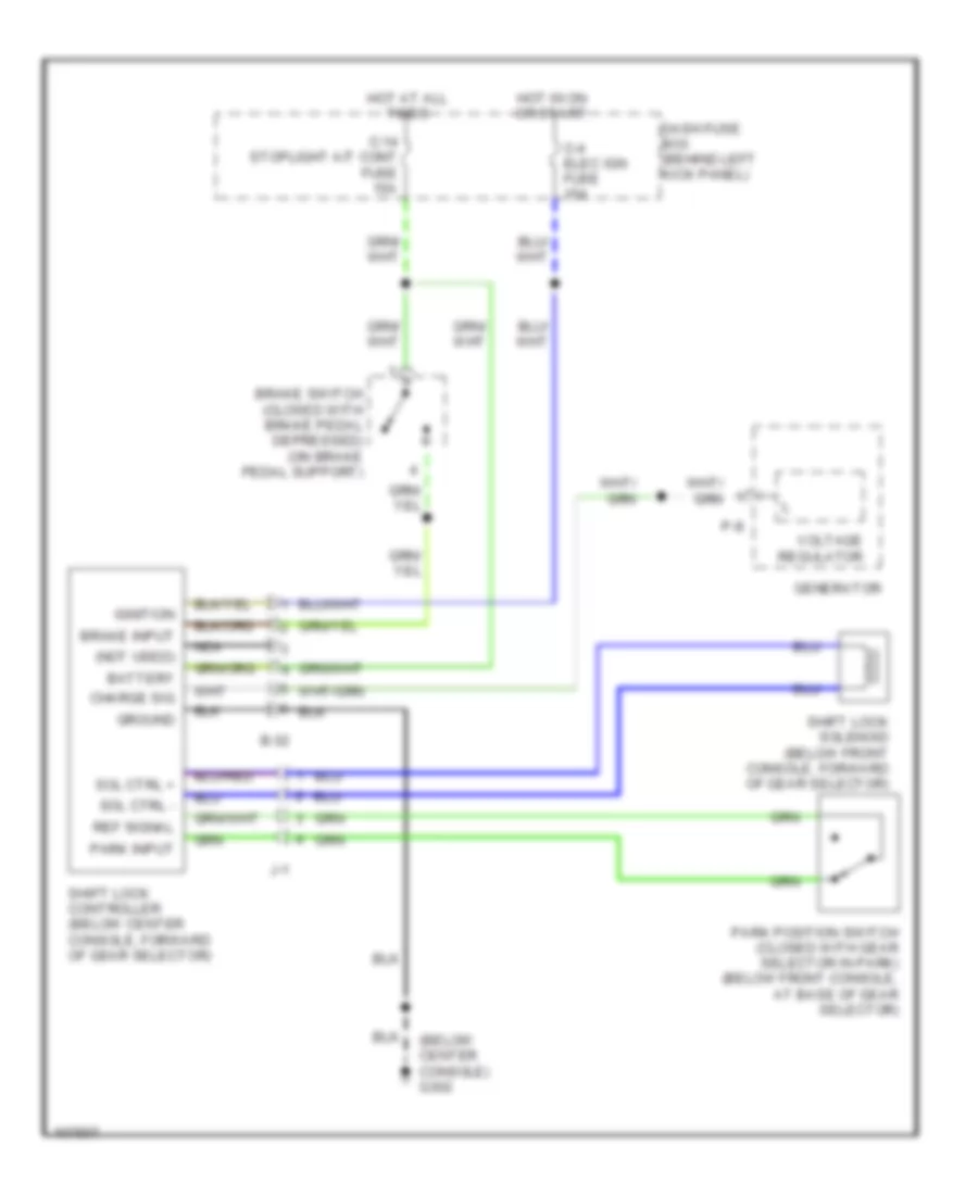
AUTOMOTIVE ELECTRICIANS PORTAL

SHIFT INTERLOCKS – Isuzu Trooper LS 1998 – SYSTEM WIRING DIAGRAMS

SHIFT INTERLOCKS

Shift Interlock Wiring Diagram for Isuzu Trooper LS 1998

Shift Interlock Wiring Diagram for Isuzu Trooper LS 1998 https://portal-diagnostov.com/license.html
https://portal-diagnostov.com/license.html Automotive Electricians Portal FZCO Automotive Electricians Portal FZCO
Get access to all wiring diagrams of the carDownload PDF file

List of elements for Shift Interlock Wiring Diagram for Isuzu Trooper LS 1998:

  • (below center console) g302
  • (not used)
  • B-32
  • Battery
  • Brake input
  • Brake switch (closed with brake pedal depressed) (on brake pedal support)
  • C-14 stoplight a/t cont fuse 15a
  • C-4 elec ign fuse 15a
  • Charge sig
  • Dash fuse box (behind left kick panel)
  • Generator
  • Ground
  • Hot at all times
  • Hot in on or start
  • Ignition
  • J-1
  • Nca
  • P-8
  • Park input
  • Park position switch (closed with gear selector in park) (below front console, at base of gear selector)
  • Ref signal
  • Shift lock controller (below center console, forward of gear selector)
  • Shift lock solenoid (below front console, forward of gear selector)
  • Sol ctrl +
  • Sol ctrl -
  • Voltage regulator