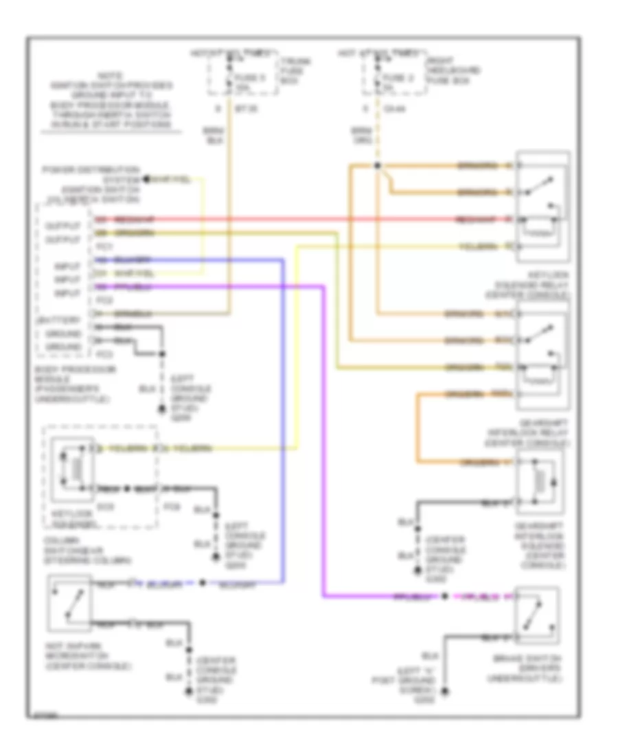
SHIFT INTERLOCKS
Shift Interlock Wiring Diagram for Jaguar XJ6 Vanden Plas 1997
List of elements for Shift Interlock Wiring Diagram for Jaguar XJ6 Vanden Plas 1997:
- (center console ground stud) g302
- (left "a" post ground screw) g202
- (left console ground stud) g206
- 10(5)
- 6(1)
- 7(2)
- 8(3)
- Battery
- Body processor module (passenger's underscuttle)
- Brake switch (driver's underscuttle)
- Bt35
- Ca44
- Column switchgear (steering column)
- Fc1
- Fc2
- Fc3
- Fc8
- Fuse 2 5a
- Fuse 5 10a
- Gearshift interlock relay (center console)
- Gearshift interlock solenoid (center console)
- Ground
- Hot at all times
- Input
- Keylock solenoid
- Keylock solenoid relay (center console)
- Nca
- Not in-park microswitch (center console)
- Note: ignition switch provides ground input to body processor module, through inertia switch in run & start positions
- Output
- Power distribution system (ignition switch via inertia switch)
- Right heelboard fuse box
- Sc6
- Trunk fuse box
 English