SHIFT INTERLOCKS
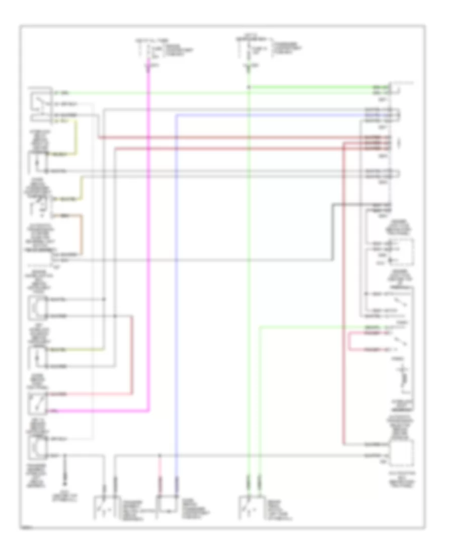
Shift Interlock Wiring Diagram for Land Rover Defender 90 1997
List of elements for Shift Interlock Wiring Diagram for Land Rover Defender 90 1997:
- Automatic transmission selector (behind center console)
- Automatic transmission starter inhibitor/ reverse light switch (above gearbox)
- Brake pedal switch (left side of firewall)
- C285
- C286
- C287
- C289
- C550
- C57
- C62
- Diode (behind dash trim panel)
- Diode (behind passenger compartment fuse box)
- Engine compartment fuse box
- Engine immobilization ecu (behind instrument pack)
- Fuse 18 15a
- Fuse 20a
- G121
- G121 (center top of firewall)
- Header joint k108 (center top of firewall)
- Header joint k109 (behind dash trim panel)
- Hot at all times
- Hot in start and run
- Interlock relay (behind front of center console)
- Interlock shift solenoid
- Key in sensor (behind instrument pack)
- Key interlock solenoid (behind instrument pack)
- Multifuction ecu (behind dash trim panel)
- Park1
- Park2
- Passenger compartment fuse box
- Transfer gearbox interlock unit (above gearbox)
- Transfer gearbox neutral switch (above gearabox)
 English