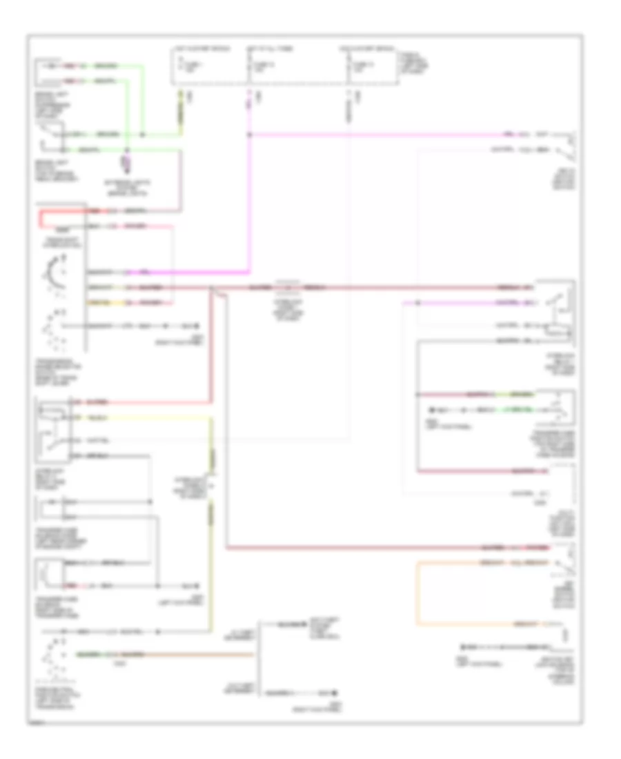
SHIFT INTERLOCKS
Shift Interlock Wiring Diagram for Land Rover Discovery SE7 1996
List of elements for Shift Interlock Wiring Diagram for Land Rover Discovery SE7 1996:
- 2 (or 1)
- Anti-theft system (theft alarm ecu)
- Brake light switch (top of brake pedal bracket)
- Brake light switch suppressor (left side of dash)
- C204
- C205
- C226
- C323
- Exterior lights system (brake lights)
- Fascia fuse box (left side of dash)
- Fuse 1 15a
- Fuse 12 10a
- Fuse 13 10a
- G200 (left kick panel)
- G203 (right kick panel)
- Hot at all times
- Hot in start or run
- Ignition key lock solenoid (top of steering column)
- Interlock diode 1 (right side of dash)
- Interlock diode 2 (right side of dash)
- Interlock relay 1 (right side of dash)
- Interlock relay 2 (right side of dash)
- Key barrel switch (ignition switch)
- Key-in switch (ignition switch)
- Multi- function unit (mfu) (left side of dash)
- Nca
- Park/neutral position switch (left side of transmission)
- Pnk/red
- Red
- Trans shift interlock sol
- Transfer case position switch (top right side of transfer case housing)
- Transfer case solenoid (right side of transfer case)
- Transfer case solenoid diode (left rear corner of engine compt)
- Transmission range selector switch (base of trans shift lever)
- W/ theft deterrent
- W/o theft deterrent
 English