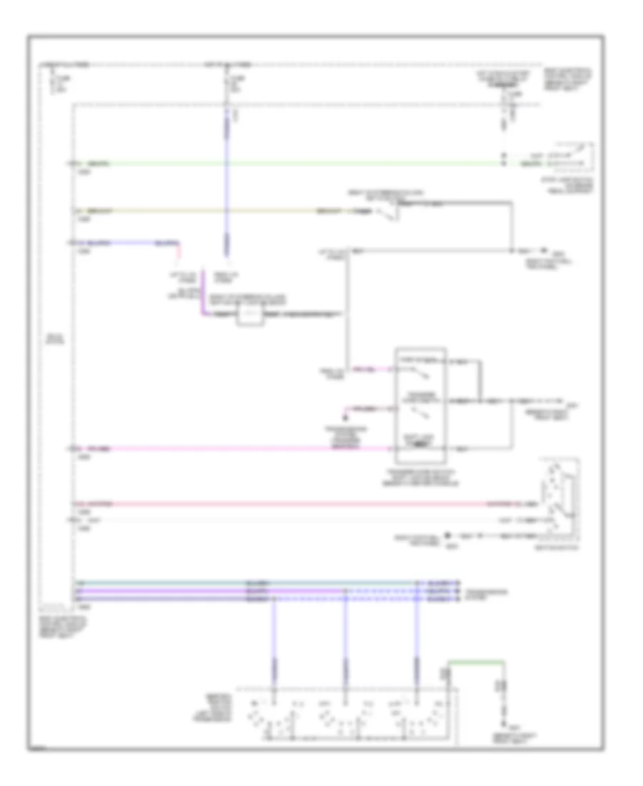
SHIFT INTERLOCKS
Shift Interlock Wiring Diagram for Land Rover Range Rover HSE 1997
List of elements for Shift Interlock Wiring Diagram for Land Rover Range Rover HSE 1997:
- (beneath right front seat)
- (right footwell trim panel)
- (right footwell trim panel) g203
- (right of steering column) ignition key-lock solenoid
- (right of steering column) key-in switch
- Body electrical control module (beneath right front seat)
- C172
- C255
- C256
- C258
- C625
- C626
- From vin
- Fuse 10a
- Fuse 20a
- G203
- G301
- Gear box position switch (left side of transmission)
- Hot at all times
- Hot in run & start (when rl10 relay energized)
- I ii
- Ignition switch
- Iii
- Nca
- Park switch
- Shift lock solenoid
- Solid state
- Stop lamp switch (on brake pedal support)
- Transfer micro switch
- Transfer micro switch/ shift lock solenoid (beneath center console)
- Transmissions system
- Transmissions system (transfer gear box)
- Up to vin
 English