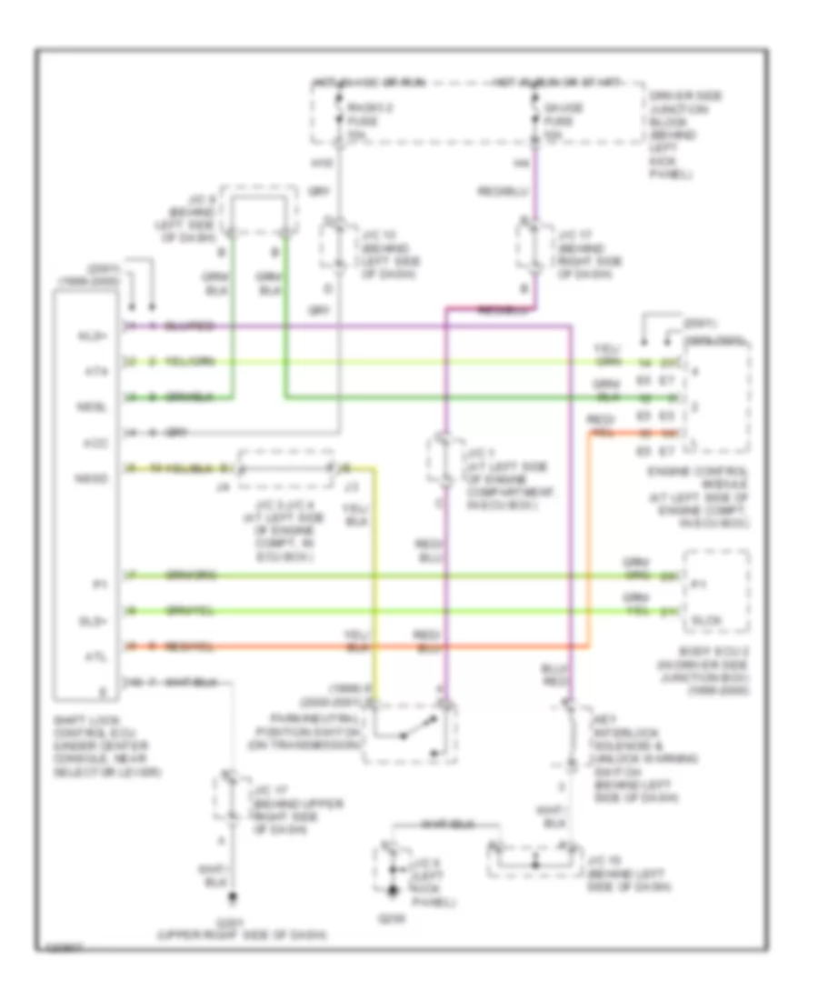
SHIFT INTERLOCKS
Shift Interlock Wiring Diagram for Lexus GS 400 1999
List of elements for Shift Interlock Wiring Diagram for Lexus GS 400 1999:
- (1999) (2000-2001)
- (1999-2000)
- (2001)
- (2001) (1999-2000)
- (upper right side of dash)
- Acc
- At4
- Atl
- Body ecu 2 (in driver side junction box) (1999-2000)
- Driver side junction block (behind left kick panel)
- Engine control module (at left side of engine compt, in ecu box)
- G200
- G201
- Gauge fuse 10a
- H10
- Hot in acc or run
- Hot in run or start
- J/c 1 (at left side of engine compartment, in ecu box)
- J/c 10 (behind left side of dash)
- J/c 13 (behind left side of dash)
- J/c 17 (behind right side of dash)
- J/c 17 (behind upper right side of dash)
- J/c 3-j/c 4 (at left side of engine compt, in ecu box)
- J/c 6 (left kick panel)
- J/c 9 (behind left side of dash)
- Key interlock solenoid & unlock warning switch (behind left side of dash)
- Kls+
- Nssd
- Nssl
- Park/neutral position switch (on transmission)
- Radio 2 fuse 15a
- Shift lock control ecu (under center console, near selector lever)
- Slck
- Sls+
 Русский