SHIFT INTERLOCKS
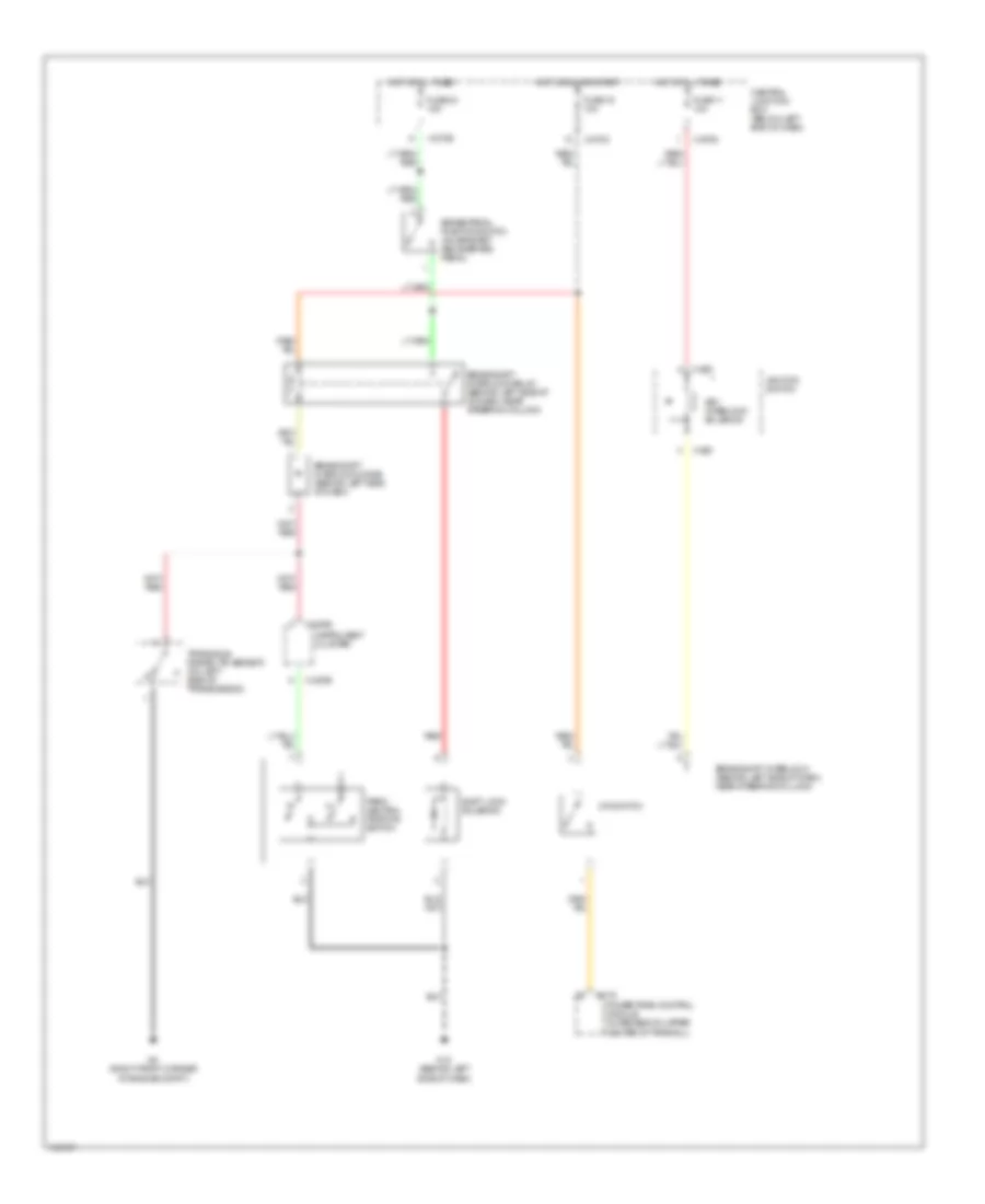
Shift Interlock Wiring Diagram for Mazda Tribute DX 2002
List of elements for Shift Interlock Wiring Diagram for Mazda Tribute DX 2002:
- B-175
- Brake pedal position switch (on bracket above brake pedal)
- Brake shift interlock diode (behind left side of dash)
- Brake shift interlock (behind left side of dash, near steering column)
- Brake shift interlock relay (behind left side of of dash, near steering column)
- C-220b
- Central junction box (below left end of dash)
- Fuse 11 10a
- Fuse 16 10a
- Fuse 24 15a
- G13 (behind left side of dash)
- G2 (right front corner of engine compt)
- Hot at all times
- Hot in run or start
- Ignition switch
- Instrument cluster
- Key interlock solenoid
- O/d switch
- Park/ neutral position switch
- Powertrain control module (in recess on upper center of firewall)
- Red
- Shift lock solenoid
- Transaxle range (tr) sensor (on left side of transmission)
- X-250
- X-270c
- X-270d
- X-270e
 English