
SHIFT INTERLOCKS
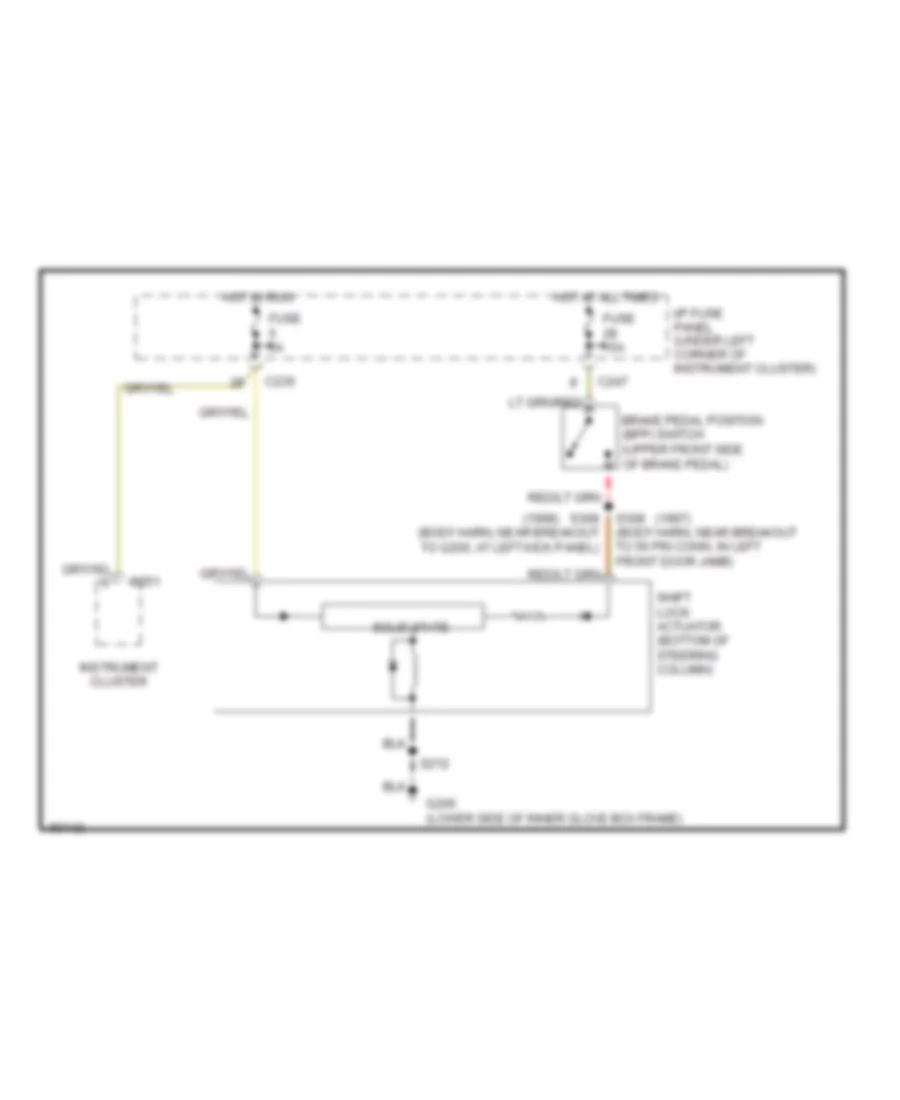
Shift Interlock Wiring Diagram for Mercury Sable GS 1997
List of elements for Shift Interlock Wiring Diagram for Mercury Sable GS 1997:
AIR CONDITIONINGANTI-LOCK BRAKESANTI-THEFTBODY COMPUTERCOOLING FANCOMPUTER DATA LINESDEFOGGERSELECTRONIC POWER STEERINGEXTERIOR LIGHTSELECTRONIC SUSPENSIONCRUISE CONTROLGROUND DISTRIBUTIONENGINE PERFORMANCEINSTRUMENT CLUSTERINTERIOR LIGHTSHEADLIGHTSHORNPOWER DOOR LOCKSPOWER ANTENNAPOWER MIRRORSPOWER SEATSPOWER WINDOWSPOWER DISTRIBUTIONPOWER TOP/SUNROOFRADIOSUPPLEMENTAL RESTRAINTSSTARTING/CHARGINGSHIFT INTERLOCKSWARNING SYSTEMSTRANSMISSIONTRUNK, TAILGATE, FUEL DOORWIPER/WASHER