
SHIFT INTERLOCKS
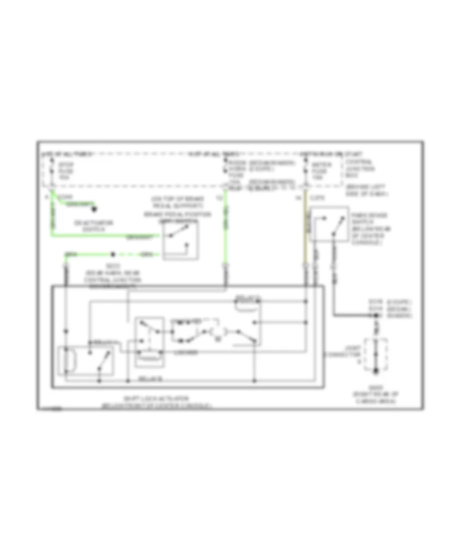
Shift Interlock Wiring Diagram for Mercury Tracer GS 1999
List of elements for Shift Interlock Wiring Diagram for Mercury Tracer GS 1999:
AIR CONDITIONINGANTI-LOCK BRAKESANTI-THEFTCOMPUTER DATA LINESCOOLING FANCRUISE CONTROLDEFOGGERSENGINE PERFORMANCEEXTERIOR LIGHTSGROUND DISTRIBUTIONHEADLIGHTSHORNINSTRUMENT CLUSTERINTERIOR LIGHTSPOWER DISTRIBUTIONPOWER DOOR LOCKSPOWER MIRRORSPOWER WINDOWSRADIOSHIFT INTERLOCKSSTARTING/CHARGINGSUPPLEMENTAL RESTRAINTSTRANSMISSIONWARNING SYSTEMSWIPER/WASHER